|

| Introduction | Estimates |
Design | Measurement | Equalization |
THOR-ORION xo |
| Construction Plans+ | SPL
limits |
Subwoofer frequency response equalization
The subwoofer is intended for the frequency range below 40
Hz, where the response of the driver in the small box rolls off considerably. An
investigation of power requirements had shown that
it is feasible to obtain maximum excursion Xmax with a reasonable size
amplifier. Therefore, equalization can make the unit
into a useful subwoofer. The amount of equalization can be estimated from the
[EQ] tab of closed-box1.xls , after the target
response has been defined in block 5 under [Spec's].
The effect of the poles
at 30 Hz and 46 Hz will be canceled by zeros at the same frequencies, in order to
bring up the frequency response. The circuit for this is shown below. It uses
the layout of the WM1 printed circuit board .
Alternatively, the Linkwitz
Transform circuit topology could have been used, since even for this case of real
axis poles the realizability criterion k > 0 in block
6 under [Spec's] is satisfied with Fp = 20 Hz and
Qp = 0.5, for example. This circuit can also be accommodated on the WM1 board.
The above asymptotic match of the measured frequency response curve indicates
poles at 30 Hz and 46 Hz, which corresponds
to F0 = sqrt(30 x 46) = 37.2 Hz and Q0 = 37.2/(30 + 46) = 0.49.
F0 is not too different from the calculated value for Fb in box 3 under
[Spec's], but Q0 is significantly higher than Qt. The values F0 = 37.2 and Q0 =
0.49 should be used in pz-eql.xls to determine
component values.
The necessary boost in gain cannot be carried too far, or
the equalizer circuit runs into voltage clipping at the power supply rails.
Since it is likely that there will be some room gain at the very low frequency
end, the response is not equalized to be flat, which helps with the clipping
concern. A subsonic rumble highpass filter would defeat the purpose of the
subwoofer. I have not found that rumble is an issue, if the subwoofer system is
designed for large voltage swings and volume displacements.
The actual low frequency response curve was arrived at
interactively, by observing the acoustic response, while modifying the two low
frequency corners of the boost. The ultimate roll-off is governed by these new
poles at 15 Hz and 6.4 Hz. The 450 Hz pole compensates for the rise in
response as the woofer becomes directional. This removes associated phase shift
from consideration when crossing over around 100 Hz.

Before the subwoofer can be used in a sound system, it
must be matched up with the existing woofer. The necessary crossover circuitry
can be constructed on the MT1 circuit board .
In my case, I am using the LFE output of the Lexicon
DC-2 processor, which has a 40 Hz lowpass function with 24 dB/oct roll-off slope
and I rely on this unit to handle the integration with the other speakers in my
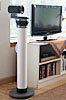
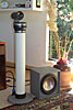
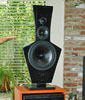
system. The two THOR units are placed together on the floor in the left front
corner of my living room.
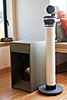
Other applications
THOR can be used as a subwoofer for the ORION
to increase its low frequency output volume. It can, of course, also serve as a regular woofer, when crossed over
around 100 Hz to a midrange. In that application it may not be necessary to
equalize it at all, since the frequency response roll-off is gradual and only 6
dB down at 30 Hz. But an active crossover is needed. The design procedure for
the crossover is as follows:
- Completely seal any vents or openings of the existing
speaker cabinet to make it a closed box. This will create a 2nd order
acoustic highpass response for the old woofer. (Merely leave a pin hole for
static air pressure equalization between inside and outside.)
- To determine F0 and Q0 of the newly created highpass
filter measure the low frequency impedance of the speaker at its binding
posts using f0Q0.gif and the [Test]
tab of closed-box1.xls .
- If F0 is less than 140 Hz and Q0 between 0.6 and 0.8,
then use F0 as the new crossover frequency value and proceed to the next
step, which is to design the circuitry for a 4th order acoustic
crossover.
If F0 is higher, or Q0 falls outside the indicated range, then things get a
bit more complicated. Q0 = 1 would make a 3rd order Butterworth filter with
the addition of an electrical 1st order highpass at F0, such as a simple RC
filter.
In other cases it may be necessary to use a pole-zero
shifting circuit to first bring F0 and/or Q0 to more convenient
values.
- With a 2nd order acoustic highpass filter at F0 and Q0
of approximately 0.7 it is only necessary to add a single electrical
highpass filter section with F0 and Q0 = 0.7 to drive the existing
speakers. The combination of existing acoustic highpass and added electrical
filter gives the targeted 4th order L-R crossover highpass response. The
electrical lowpass filter that drives the woofer power amplifier requires
two sections to achieve a 24 dB/oct roll-off. Component values are
calculated from
F0 = 1 / (8.89 R C)
- Left and right channel crossovers can be build up on a
single MT1 circuit board by loading only the
necessary components. In this application of the pcb it is preferable to
jumper wire the gain control section into the woofer signal path.
- With the crossover connected between preamplifier and
power amplifiers use a 100 W or larger solid-state stereo power amplifier to
drive the two woofers that have been added.
- When considering to build the power amplifiers
yourself, then investigate the SANYO STK4050
thick film hybrid IC. It is capable of 200 W output and costs around $20 at Consolidated
Electronics. See also the LM3886 IC
amplifier suggestions for the PHOENIX.
| Introduction | Estimates |
Design | Measurement | Equalization |
THOR-ORION xo |
| Construction Plans+ | SPL
limits |
| 


