|
When a new loudspeaker looks different from what is
conventionally expected or what experts in loudspeaker design consider to be
reasonable, then this raises questions, expectations and conclusions based on
speculation, previous experience, understanding or a personal agenda.
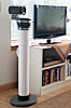
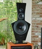
I consider the LX521 to be my best design in a long search
for an electro-acoustic transducer, which can set up in a domestic size room a
realistic seeming illusion of an acoustic scene, while perceptually moving the
loudspeakers, the room's resonances, reflections and reverberation beyond one's
acoustic horizon. The LX521 was designed for easy construction and low cost in
keeping with its acoustic performance goals. Only in a few areas could I have
made different design choices, but I had my reasons for not doing so. Your
questions may bring these to light.
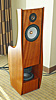
As DIY loudspeaker builders you may have your own ideas.
Pursue them and not just in your mind. Design, build, listen and compare to
live, unamplified sounds. Learn from the LX521 by building it as designed first
and then modifying it. I have learned from my previous work, which you can study
on this website. There are also ORION FAQ and PHOENIX FAQ pages with relevant questions about dipole
speakers. I have learned from what I heard at shows, from what others have
demonstrated to me or talked about on the web, at conferences, in books and
publications. To that I add my own thoughts and experiences. The LX521 is the
result.
I strongly recommend to build the LX521 per instruction.
Set up the loudspeakers in your home for enjoyment or in the recording studio for
work. I very much hope that these transducers will be used by recording, mixing
and mastering engineers to further the quality of recordings.
Q1 - How do they sound?
A1 - They render the phantom acoustic scene with greater
clarity, presence and realism than the ORION. Loudspeakers and room readily
disappear. Microphone techniques and spatial rendering consequences show up
clearly. Sound-wise they are completely neutral from top to bottom. They
emotionally engage the listener with the music, the instruments, the performers
and their acoustic surroundings, making music listening more effortless and
pleasurable.
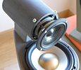
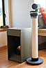
Q2 - I do not like the appearance
of the top baffle and want to change it slightly
A2 - Don't change it. Try to get used to it. The
midrange/tweeter baffle is an essential acoustic design element. It controls the
interference between between front and rear radiated sound waves in order to
obtain a dipolar radiation pattern over the whole frequency range. Thus baffle
dimensions must be measured in fractions of radiated wavelength and how much
phase shift is produced. For example, at 7 kHz the wavelength is 49 mm. Every mm
causes 3600/49mm = 7.350 of phase shift . The 19 mm thick
baffle introduces 1400 of phase shift between front and rear
radiation on-axis. At increasing off-axis angles this phase shift becomes less,
but the varying width of the baffle also contributes to the total phase shift
and to the summation of front and rear radiated waves at points in space around
the loudspeakers.
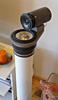
Q3 - I want to use a 1 inch thick
top baffle and recess the midrange drivers
A3 - The top baffle was not designed for this and ideally should be
even thinner than the 3/4" wood chosen for mechanical strength and ease of
construction. The upper midrange part of the baffle has the most critical
dimensions. See A2. The driver mounting hole should not be chamfered, because it
could affect the polar response and baffle strength. The baffle could be milled
out of 1" thick wood or other material according to its 3-dimensionally
specified dimensions.
Q4 - I think eliminating the
passive crossover and driving lower and upper midranges separately and from an
active crossover of higher order might yield
higher performance
A4 - Maybe, maybe not. I have not tried it. When I
started the design I was looking for a midrange driver and baffle combination
that would extend dipole behavior into the kHz frequency range and still allow
for a 3-way design with a dipole woofer below 150 Hz. Furthermore I wanted a
dipolar tweeter with wide vertical dispersion. I could not find a midrange drive
unit that met my needs at low and high frequencies simultaneously. Thus the two
chosen drivers. They provide a wide frequency overlap range, conducive to a
first order crossover, to gradually merge the two midrange dipoles into one. In
essence I turn the two into a single, very broadband midrange dipole with low
group delay variation. The smaller driver does not show signs of stress at its
low end, nor does the larger driver show signs of harshness at its high end. A
passive crossover network brings with it the convenience of not having to
redesign the ORION ASP printed circuit board, which I now also use for the LX521
ASP.
At some point in the future I might do a new layout of the board and add a first
order (or higher?) crossover to have the option of a fully active 4-way speaker.
But right now I am totally unmotivated, because I have no evidence of practical
benefits and only of further work. For example, the frequency response due to
the passive crossover is determined by the driver and network impedances and
would require modification of the midrange equalization for an active crossover.
Also, there is no 10-pole Speakon connector available or a 5-conductor-pair
speaker cable.
Q5 - Will you offer a DSP based
crossover/equalizer?
A5 - A DSP based xo/eq makes a lot of sense for manufacturing
and cost reasons. For the DSP to become the sonic equivalent of the LX521 ASP
will require a lot of attention to design and performance details in the digital
and analogue bowels of the beast. I am not an expert in DSP application
programming or even know how to chose the most suitable DSP engine. It is not on
my priority list at this time.
Update - Since I wrote this Dave Reite and others have responded to the DSP
challenge and designed a DSP version of the ASP. I have used a miniDSP 2x4
for the LXmini xo/eq design and what I learned from that inspired me to apply
the miniDSP 4x10 HD to the 4-way LX521.4 and LXstudio speakers. I am sold on DSP
and glad not to have to deal anymore with parts procurement issues for an ASP
solution.
Q6 - Are you done with designing
the LX521?
A6 - Yes. The LX521 has met and exceeded my expectations. I have
lived with it and used it now for nearly five months. Every visitor to my home,
whether trained listener or audiophile, is excited. I own the only speaker pair
in existence and I have not yet seen the production versions of the two midrange
drivers. Based on previous experience with SEAS I expect the drivers to be
duplicates of the prototypes, which I use. Thus no change to the design. I also
have not yet seen the baffle flat-pack, but it will meet all specified
dimensions and cause no changes to the ASP design. The ASP itself is documented
and parts are available to duplicate it.
I have heard loud voices on the Internet chiding me for presumed flaws in my
design or being late to some party. For whom should I feel sorry? I am free to
design as it pleases me, to change course and also to stop.
Q7 - Can the sound be improved by
using a different material for the top baffle?
A7 - I do not know since I have not tried, nor have I found a
reason for trying. A different material could mean using a material with
different mass, stiffness and damping properties, but preserving the outline
and thickness of the prototype baffle. In such case the acoustic wave launch
and guide properties of the baffle would remain unchanged, but the mechanical
vibration characteristics of the baffle might be different. Thus, any spurious
radiation due to baffle vibration might be different, but it is not known
whether there exists a problem to be solved or whether a problem would be
introduced. The dominant vibration mode for the top baffle is formed by the
upper midrange and tweeter section swinging back-and-forth relative to the lower
midrange section. The narrow neck above the lower midrange forms the pivot axis.
This is a low frequency bulk movement, which the bridge over the woofer baffle
largely prevents from becoming excited. I have no evidence that this
vibration mode has audible consequences, even when the top baffle rests directly
on the woofer baffle.
A baffle material with different thickness is highly likely to change the
acoustic wave launch and guide properties of the baffle, affecting particularly
the upper midrange and tweeter baffle section. Thus the optimum baffle contour
for the given drivers would have to be re-determined by acoustic free-field
measurements. Ideally the baffle would be very thin and the drivers would be
dipole point sources to minimize front-to-back distance. In reality the
drivers have too much physical depth and width relative to the wavelength they
are meant to radiate. Baffle outline and thickness are then used as parameters
for finding a practical solution for broadband dipolar radiation with a given
set of drivers. The LX521 top represents clearly not the only possible baffle
shape, but is an engineering and cosmetic trade-off that works well and is easy
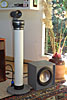
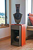
to build. The whole speaker is not a piece of furniture but should be viewed as
an interesting, purpose-built sculpture that blends in visually, without
imposing its presence. Once the music plays it disappears from attention.
It should be obvious that changing to a different midrange or tweeter driver is
likely to also require a different baffle shape and equalization.
Q8 - What cables and interconnects do you recommend?
A8 - I prefer not to
recommend any specific product. Cables can have audible effects and some
manufacturers make sure they will, either through unusual electrical parameters
and/or by suggestion. Weaknesses in the design of
the output-to-input interface are exploited. In any case, sounding different does not
automatically mean that you now have a more accurate transfer from electrical to acoustical
output.
Realize that for an active speaker, such as the LX521, each power amplifier
essentially sees a voice coil, either of the tweeter, midranges or woofers driver, and
that is an easy load to drive. The
speaker cable capacitance and inductance have insignificant influence upon
the voltages across the voice coils of lower and upper midrange drivers with the
large crossover inductor and capacitor in the signal path.
My guideline for speaker cables is to keep their resistance to less than 0.1 ohm
for the roundtrip path of the current. This defines the maximum length of a
2-conductor copper cable for different wire gauges.
| Wire gauge |
Max. length in feet |
| 18 |
8 |
| 16 |
12 |
| 14 |
20 |
| 12 |
30 |
| 8 |
80 |
I measured the 16 gauge Megacable from Radio
Shack (278-1270) that I use. A 10 foot length has 0.07 ohm resistance, 714 pF of
capacitance and 1.9 uH of inductance. The line impedance is 51 ohm. A typical
tweeter has a voice coil resistance of 4.7 ohm and 50 uH inductance. At 20 kHz
this yields an impedance of about |4.7 + j6.3| = 7.9 ohm. Add to this the
cable inductance of j0.24 ohm, and 0.07 ohm resistance for 10 feet, and the
impedance becomes 8.09 ohm. This causes a 7.9/8.09 = 0.98 or 0.17 dB reduction
in tweeter output at 20 kHz, which is insignificant. The cable effect is
even less at lower frequencies.
Speaker cables can act as antennas in the AM
frequency band and may cause distortion in the output stage of a solid-state
amplifier, if strong radio frequency signals are present. In particular, the
cable capacitance in conjunction with the inductance of a driver voice coil may
form a resonant circuit for these frequencies. The resonance can be suppressed
by placing a series R-C circuit of 10 ohm/2 W and 0.33 uF/100 V across the cable terminals
at the speaker end.
Coaxial interconnects with phono (RCA) plugs tend to pick up
radio frequencies in the FM band. The currents that are induced in the cable
shield must not be allowed to enter the inside of the coax. This requires a very
low resistance connection between the outer conductor of the phono connector and
the chassis (signal ground) of the equipment that it plugs into. The continuity
and low resistance of the shield is also very important for hum and buzz
currents, so that they will not induce a voltage on the center conductor. The
technical description for this is the Transfer
Impedance of the cable and connectors, which must be in the low milli-ohm
range. Unfortunately I have not seen this specification used by the audio
industry. An excellent description of the theory and treatment of hum and buzz
problems in equipment setups with mixed two and three prong AC plugs is given in
AN-004 by Jensen
Transformers, Inc. I have not found balanced interconnections to be necessary
for the high level circuits past the preamplifier. But sometimes it requires to
experiment with AC outlets in different locations to reduce to insignificant
level the buzz that one may hear with the ear close to the speaker cone. So,
when choosing a coaxial audio interconnect look for good mechanical
construction, direct contact between shield and connector, and well plated
contact surfaces.
I find what is needed at Radio Shack. I
solder speaker cables to terminal strips on the speaker end and use dual in-line
banana plugs on the amplifier end.
See also "Dealing
with legacy pin 1 problems" and "Shield
current induced noise" for solving hum and RFI problems.
Q9 - Can I drive the
LX521 as a 4-way?
A9 - Yes, you could drive the lower mid by its own amplifier through
the specified inductor. Likewise the upper mid would then be driven through the
specified capacitor from a another amplifier. The two amplifiers are both driven in parallel from the
midrange output of the ASP or DSP All amplifiers in the 4-way system must have identical
voltage gains.
The DSP, but not the ASP, could also be configured for 4-way outputs. This would
eliminate the inductor and capacitor and change the sound unless the DSP
emulates the driver terminal voltages with the passive xo installed. See
investigations done at the OPLUG.
Q10 - What is the
voltage sensitivity of the LX521?
A10 - I heard this question several times at RMAF-2013 and usually by
people who own low power amplifiers, which they like for their sound. If those
are tube amps, then they are not appropriate for the LX521 because I designed
the ASP with power amplifiers of much less than 1 ohm output impedance in mind.
That is solid-state amplifier territory. Furthermore output power transformers
in tube amps do not reach down to 1 Hz as would be desired for the
woofers.
The attraction is probably the lower and upper midrange drivers which cover 120
Hz to 7.5 kHz with a 1 kHz 1st order passive crossover. The SEAS specified
voltage sensitivities for 2.83 V (= 1 W into 8 ohm) and 1 m distance are:
Lower midrange U22REX/P-SL (H1659-08) = 90.5 dB
Upper midrange MU10RB-SL
(H1658-04) = 84.7 dB
It is difficult to predict, without measuring the maximum peak-to-peak voltage
across each driver terminal, how much power is needed for different program
materials at maximum listening levels. I use 180W (AT1806) at home, and with no
power issues 60W (AT6012) at BAF-2013 and 200W (Emotiva XPA-5) at RMAF-2013. If
lower power amplifiers are used they must be well behaved when driven into
voltage or current clipping and not develop momentary dc offsets or high
frequency oscillation.
All power amplifier channels must have identical voltage gain. If not available,
then 2-resistor attenuators must be loaded into the ASP output circuitry to
reduce higher amplifier gain channels to the lowest power amplifier's voltage gain.
Click on ORION-FAQ
or PHOENIX-FAQ, if you did not find your answer above
Check out the ORION/PLUTO/LX521 Users
Group for knowledgeable
advise
CAUTION:
The content of any page may change without notice
as I learn new things or find better descriptions. The designs presented here
may change as I make new observations or gain more insight. Audio has overwhelmingly been a hobby for me, for my own pleasure and love of
music. I enjoy to share what I found and possibly to dispel a few
misconceptions. My interest is not on the business side, though I like that my
activities pay for my hobbies. You may not agree with some or all aspects of my
designs, the approach that I take to them, or the theories. I have no problem
with that. Just do not ask me "what would happen if ...". Changes that
you make to the designs are for your own pleasure and at your own risk. But if
you learn something worthwhile, then please let me know. My DIY projects are not
for beginners and it may be necessary for you to buy subassemblies or a turnkey
system. Please do not ask me for individual help with your
DIY difficulties. All my designs have a Support Page. It is listed on the cover
or inside your project documentation. There is an ORION/PLUTO/LX521 Users
Group with people who can help you. I respond to every email eventually, but
you may not get the answer you want. I consider my writings in these web pages
as brief and to the point. I labor over every sentence and word and provide
little redundancy. I am not a native English speaker. I grew up in Germany. Read thoroughly and maybe more than once. I do not write for
the rank beginner, but for those who have been around the block. You may need to
study up. The links in my text are for that. I have not been standing still
since I started this website in 1999 with the idea of a brain dump of my
previous findings so they would not get lost to the audio community. In 2006,
after PLUTO, I thought I would go into a support and maintenance mode. No new
design. Stuff happened, more work to be done on radiation patterns. Also the recording and rendering
process interested me. Therefore the LX521. It brings to completion my search
for the prototype of an ideal stereo loudspeaker. It has confirmed theories and
observations of how we hear in reverberant spaces The auditory illusion is
convincing. I am satisfied. It's time to enjoy the
sublime magic of sound and space! - January, 2014
|