|
|
|
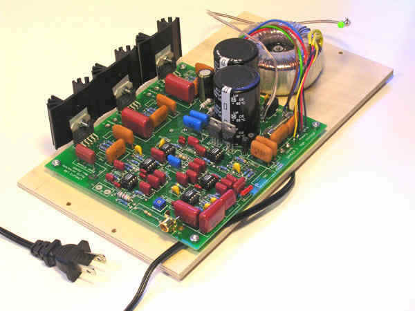
Power amplifier, crossover and equalizer
|
 |
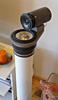
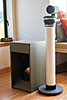
The raw on-axis response of the pipe mounted tweeter which obviously must be equalized. |
 |
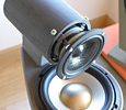
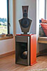
The raw frequency response of the upward pointing woofer when mounted in the pipe and measured at 90 degrees from the vertical direction as a listener would hear it. The fine grain is not of concern at this point. Most of it is due to the test environment. |
 |
The frequency response of the woofer after it has been equalized, when measured close to the dust cap. |
 |
The frequency response of the final electronics, when measured at the amplifier outputs. 6 dB must be added to the woofer curve to see the true woofer terminal response. Only one side of the bridged amplifier output was measured with respect to 0 V. The other side has the same response, but is 180 degree phase shifted. |
The complete circuitry is shown below. The input buffer stage drives tweeter and woofer channels. It can handle low level signals from a preamplifier output or high level signals from a power amplifier output. The tweeter channel has a gain control stage which is linear in dB. It is followed by the two stages of a 4th order Linkwitz-Riley highpass filter and then an allpass for correcting the phase shift due offset in acoustic centers between woofer and tweeter. The notch filter equalizes a peak in the tweeter response. The last stage is the power amplifier.
The woofer channel starts out with two LR4 lowpass filter
stages, They are followed by a biquad circuit which in this case is only
partially utilized for equalization. It was included on the circuit board for
other possible applications. Next is a notch filter which shunts the signal
going to the buffer stage before the bridged power amplifiers. This buffer stage
drives one of the power amplifiers directly and the other one through a unity
gain inverting stage. Thus the voltage across the woofer terminals can swing up
to +/-60 V peak.
All power amplifier stages utilize the high-performance
National Semiconductor LM3886 integrated circuit.
This IC clips cleanly and is
protected thermally and against current overload. Not only that, but a well
designed chip amplifier has an inherent performance advantage over a discrete
component solid-state amplifier, because its output bias circuitry is directly
on the silicon chip and thermally tracks output stage parameter changes due to
fluctuating amounts of program power and continuous chip temperature change.
Such accurate tracking is very difficult to obtain with discrete designs where
temperature sensing can only be accomplished outside the output device packages.
The thermal time constants of sensor and chip must be equal. Lack of thermal
tracking is the prime source for increased crossover distortion at low output
power levels and results in high order distortion products which have given many
class A/B solid-state power amplifiers a bad name as sounding gritty. The
distortion should be measured with dynamic test signals, not steady-state
signals as is common practice when characterizing amplifiers.
The operational amplifiers are
Burr-Brown/Texas Instrument OPA2134. They are quiet and have very low
distortion.
The power supply utilizes a 50 W transformer that can be
wired for either 115 VAC, 60 Hz operation with the two primary windings in
parallel, or for 230 VAC, 50 Hz line voltage with the windings in series. The
presence of power line voltage on the circuit board requires caution when
testing to avoid dangerous electrical shock.
The return currents of the three power stages go to the 0 V terminal and are run
separately from the signal ground of the line level stages in order to avoid
amplifier low frequency instabilities. Positive and negative regulators provide
stable and clean voltage to the operational amplifiers.

| Introduction |
Specifications | Construction |
Electronics | Supplies | Photos
| Pluto-2.1 |
|
| ||||