|
|
|
Crossovers--- Crossovers --- Linkwitz/Riley --- Active filters ---
Crossovers
It is practically impossible for a single
radiator to cover the 20 Hz to 20 kHz audio frequency range at adequate sound
pressure levels (SPL) and with wide dispersion off-axis. At a 50 Hz bass
frequency, for example, it takes an air volume displacement of 214 cm3
to generate 90 dB SPL at 1 m distance from the source in free space. Take a typical 6.5
inch (132 mm effective) diameter driver and its cone would have to move 14 mm
peak-to-peak linearly, which by far exceeds its excursion capability (Ref.
4). The proper crossover of signals from one driver to the next is a subject of debate amongst audiophiles with some preferring a1st order Butterworth filter function . As often done, a single capacitor and resistor in the connection to the tweeter will not necessarily create a phase-linear 6 dB/octave crossover, but more something like a 18 dB/oct. acoustic response due to the inherent 12 dB/oct. highpass behavior of the tweeter itself. Furthermore, the tweeter will contribute a good amount of intermodulation distortion because the cone excursion wants to rise at 12 dB/oct. towards lower frequencies for constant SPL and the driver is not built for that. Add to this the wide frequency coverage overlap between tweeter and midrange, with the resulting irregular polar radiation pattern, and the 6 dB/oct. crossover becomes a costly solution for achieving waveform fidelity. At best, the goal may be obtained over a very small region in space and over a limited frequency range. But, does it matter to the listening experience, given some common observations? Networks that divide the electrical audio signal between different drivers must be designed with the driver characteristics and the driver layout in mind in order to obtain the desired acoustic crossover function and polar radiation pattern in conjunction with tolerable non-linear and linear distortion of the acoustic output. All crossovers involve design tradeoffs. For the Audio Artistry Beethoven-Elite system, for example, I used 24 dB/oct. and 12 dB/oct. Linkwitz-Riley (Ref. 17) and 6 dB/oct. Butterworth acoustic crossover filter responses. My latest design, the ORION, employs two 24 dB/oct filters for highest accuracy of perceived sound. I have a strong preference for line level active dividing networks ahead of the power amplifiers (Ref. 2, 12, 17). In this approach the power amplifier output is connected directly - except for a very low resistance speaker cable - to the voice coil of the driver. The amplifier takes maximum control over the motion of the speaker cone which gives a greater sense of clarity and dynamism compared to a passive dividing network between amplifier and driver. Active crossovers make much more effective use of amplifier power. A clipping woofer amplifier is not seen by the tweeter, which has its own amplifier. The clipping of the woofer amplifier may not even be noticed in this case. It would surely be heard with a passive crossover, where it might even overheat and damage the tweeter, because of the large amount of high frequency energy in the clipped signal. Crossover filters for a speaker usually incorporate frequency response corrections for the individual drivers to obtain a desired overall response. The active network has the advantage of correcting easily for different sensitivities of drivers and equalizing not only the individual drivers but the combined response as well. Not having to deal with the interaction between driver impedance and passive filter network gives the designer of an active crossover/equalizer much greater freedom and control to develop a superior product. ------------------------------------------------------
The Duelund 3-way crossover filter function D3Recently I received an intriguing paper of the late Steen Duelund from one of his admiring followers. Steen, a "Danish Speaker Maniac", gives a fun derivation of known crossover filter functions for the mathematically inclined and he found some novel ones. To follow his text more easily I rewrite some of it here and develop it further to show a potentially useful 3-way allpass crossover filter. A) Transient-perfect crossovers 1) - First order crossover with 6 dB/oct slopes for highpass and lowpass filters = Butterworth, B1+ H1(s) = (s + 1) / (s + 1) = 1 where s = s
+jw and the pole at sp
= -1 and zero at sz
= -1 cancel each other 2) - Second order crossover by squaring H1(s) ==> Baekgaard (H1)2 = (s2 + 2s + 1) /
(s + 1)2 Highpass and lowpass filters have 12 dB/oct slopes, but the filler bandpass filter has only 6 dB/oct slopes and is difficult to realize. At the crossover frequencies w1 = 0.5 and w2 = 2 the three outputs are not in phase and the axis of the vertical polar pattern will tilt when the three separate drivers are aligned vertically. This can be avoided by using two filler drivers in a W-F-T-F-W arrangement instead of W-F-T. More practical solutions of transient-perfect crossovers are based on delay derived crossovers where HP(s) = e-sT - LP(s) [2] or they are constructed from lowpass and highpass filters which overlap in the crossover region in such a way that a minimum phase response is preserved [3]. Their summed response is not flat, but since it is minimum phase it can be equalized. Steeper slopes can be obtained from these two types of crossovers, but the lack of in-phase addition in the crossover region tends to require symmetrical driver arrangements. For further study I recommend:
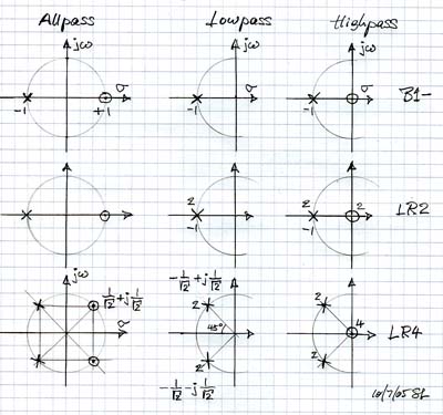
B) Allpass crossovers 3) - First order crossover with 6 dB/oct slopes for highpass and lowpass filters = Butterworth, B1- H2(s) = (s - 1) / (s + 1) = 1ejf when s = jw, i.e. the magnitude is one, but there is phase shift F(w) The pole at sp = -1 and zero at sz = +1 do not cancel but form a 1st order allpass. 4) - 2nd order Linkwitz-Riley filter (12 dB/oct, LR2) H2 H1 = (s - 1) (s + 1) / (s +1) (s
+ 1) = (1 - s2) / (s + 1)2 HP and LP are 2 x 90 degrees out of phase at all frequencies and the polarity of one driver must be reversed to obtain allpass behavior. 5) - Squaring H2(s) and going to a more general expression by replacing '2' with 'a' (H2)2 = (s2 - 2s + 1) /
(s2 + 2s +1) 6) - 4th order Linkwitz-Riley filter (24 dB/oct, LR4) by squaring H3 (H3)2 = (s2 - as +1)2 / (s2 + as +1)2 = [s4 - s2(a2 - 2) + 1] / (s2 + as + 1)2 Let a = sqrt(2) = 1.41, then H4 = (s4 + 1) / (s2 +
1.41s + 1)2 ==> 2-way HP4 = s4 / (s2 + 1.41s + 1)2 and LP4 = 1 / (s2 + 1.41s + 1)2 HP and LP are 4 x 90 degrees out of phase at all frequencies, i.e. they are in-phase.
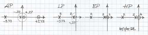
7) - Let a = 4 in (H3)2 to obtain a 3-way allpass crossover H5 = (s2 - 4s +1)2 / (s2 + 4s +1)2 ==> 3-way This is an allpass with two real axis poles at -3.73 and two at -0.27. It has real axis zeros at +/-3.73 and +/-0.27 which combine to two 1st order allpasses. The numerator of the polynomial is [s4 -s2(a2
- 2) + 1] = s4 - 14s2 + 1 HP5 = s4 / (s2 + 4s +1)2 LP5 = 1 / (s2 + 4s +1)2 Crossover is at -6 dB points and the drivers are in phase so there is no tilt in the polar response. The filter slopes should be steeper though to make the crossover more realizable.
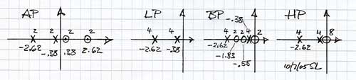
8) - Squaring (H3)2 once more leads to (H3)4 and selecting a = 3 gives the allpass H6 = (s2 - 3s +1)4 / (s2 + 3s +1)4 There are 8 poles as calculated from (s2 + 3s +1)4 = 0, four at sp1 = -2.62 and four at sp2 = -0.38 Expanding the numerator yields (s8 - 14s6 + 51s4 - 14s2 + 1) and thus the numerator for the bandpass function becomes NBP = -14s2 [s4 - (51/14)s2 +1] with two zeros each at sz1 = -1.83, sz2 = -0.55 and sz3 = 0 The individual filter functions are: LP6 = 1 / [(s + 2.62)4 (s +0.38)4] HP6 = s8 / [(s + 2.62)4
(s +0.38)4] BP6 = -14s2 (s + 1.83)2
(s + 0.55)2 / [(s + 2.62)4 (s +0.38)4]
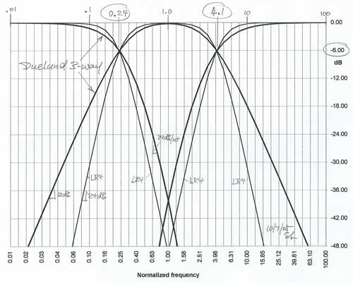
9) - It is interesting to compare this Duelund
3-way filter function to a crossover that uses LR4 filters. The crossover
frequencies must be at w1
= 0.24 and w2 =
4.1 and thus the LR4 poles are located at The filter functions become LPLR4 = 0.244 / (s2 + 0.34s + 0.242)2 BPLR4 = 4.14 s4 / [(s2 + 0.34s + 0.242)2 (s2 + 5.8s + 4.12)2] HPLR4 = s4 / (s2 + 5.8s + 4.12)2 The sum of the three filters is approximately allpass since the two crossover frequencies are far (1:17) apart.
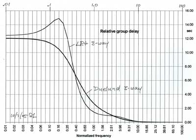
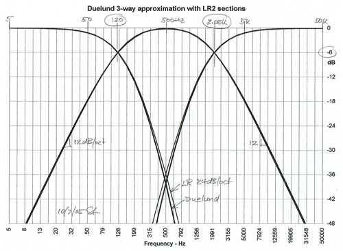
The Duelund filters roll off more gradually through the crossover region though highpass and lowpass reach 24 dB/oct slope. The bandpass covers a wider frequency range due to its more gradual 12 dB/oct roll-off. The group delay of the 3-way also reflects this relative behavior. In particular the Duelund does not show any peaking because the allpass filter sections are 1st order squared. Based on my experimentation with 1st and 2nd order allpass crossovers this visually smoother response has no audible benefits since the amount of peaking is very small.
The frequency response curves and the group delay were determined in a spreadsheet using the methodology shown in 12db-hpf.gif. 10) The Duelund 3-way is based on an 8th order polynomial yet the maximum slopes are only 4th order over the first 40 dB of attenuation. It seems likely that the same response can be approximated with 4th order functions. The good match, which was arrived at by an educated guess, can be seen in the graph below.
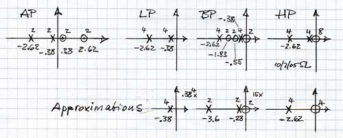
In the s-plane representation one can see the dominant poles taking over and cancellations of several adjacent pole-zero pairs.
Thus a practical Duelund 3-way crossover would have parameters like this:
Note that all mathematical functions are meant to describe the acoustic response of a 3-way loudspeaker. To the extend that woofer, midrange or tweeter drivers have a non-flat frequency response they must be either equalized to be flat, or their response must be made part of the filter function. In particular, the midrange driver's natural low frequency roll-off could be equalized with a "Linkwitz Transform" to obtain the desired LR2 highpass behavior of c) above. The tweeter can be treated similarly for two of the poles of d). The woofer's natural highpass behavior causes a phase lead which is probably far from zero at the first crossover frequency and thus affects the proper addition of woofer and midrange outputs. This can be corrected by placing a 1st order allpass in the midrange channel which simulates the highpass phase shift of the woofer. The Duelund 3-way crossover could provide a useful option for building a loudspeaker. See also:
|
|
| ||||