
| Build-Your-Own | Main Panel
| Dipole Woofer | Crossover/EQ
| Supplies |
| System Test | Design Models
| Prototypes | Active Filters
| Surround | FAQ |
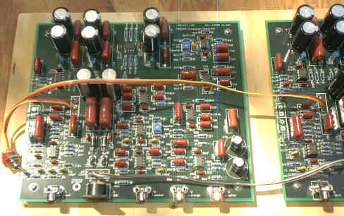
Operational amplifier circuitry generates the crossovers
between tweeter and midrange, midrange and woofer, and equalization for the 3-way,
open-baffle loudspeaker.
Crossover frequencies are set to 100 Hz (12 dB/oct L-R) and 1400 Hz (24 dB/oct L-R). The 6 dB/oct
open-baffle diffraction slopes of woofer and midrange
are equalized and also the half-space to full-space transition between
floor mounted woofer and free standing midrange. Psycho-acoustic equalization is
provided for the 3 kHz region.
Circuit behavior is described by the following functional
block diagram.
The electronic circuit diagram for implementing the above
functionality is shown below.
Download the 38xo_eq1.gif file
to resize the circuit schematic on your computer for printout.
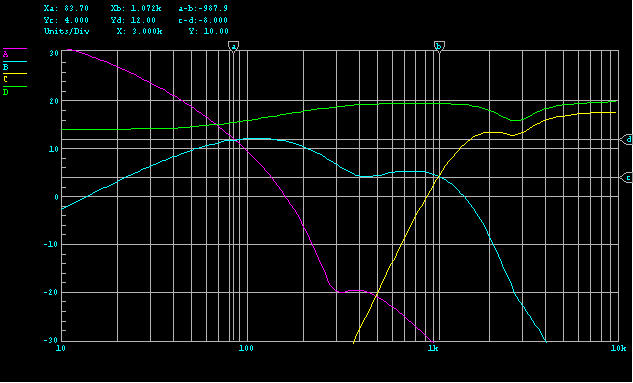
Calculated frequency response curves for buffer, tweeter, midrange and woofer
outputs can be seen in xo_eq2.jpg. Subtract a 20 dB graph offset from the vertical scale to obtain the true gain values. You will find measured frequency response data on the |
Test
| page.
Circuit description
The circuit description follows the signal path from input
to the three outputs.
140kLP -6dB - Low-pass filter to block radio frequency
interference. 6dB attenuation to compensate for the following 6 dB gain stage.
100-200HP and +6 dB - Shelving high-pass filter with 6 dB
gain to transition between
the woofer on the floor radiating into half-space and the main panel radiating
into
full-space. - shlv-hpf.gif
2760NF - Notch filter to account for differences in the
ear's free-field and diffuse-field response and differences between sound pressure pickup in recording and
playback environments. - inductr1.gif,
Design Models - H
Buffer - Low impedance drive source for the following
three channels.
Tweeter channel:
1440HP - First high-pass filter section of 24 dB/oct, 1400
Hz L-R acoustic crossover to midrange. - xo12-24.gif
+/-2.5dB - Gain adjustment with 5 dB range and precisely
linear dB scale. The preceding two resistor ladder sets the channel gain and provides a nominal 3.5k driving impedance to obtain a 5 dB adjustment range. - gain-adj.gif
1440PH - Two phase shifting all-pass delay networks to
compensate for acoustic phase differences between tweeter and midrange outputs in the overlapping
crossover frequency range. The phase shift difference results from the tweeter's voice coil being in front of
the
midrange voice coils and the tweeter's high-pass response. - allpass.gif
1440HP - Second high-pass filter section of 24 dB/oct, 1400
Hz L-R acoustic crossover to midrange. - xo12-24.gif
Midrange channel:
1440LP - Two low-pass filter sections for 24 dB/oct, 1400 Hz L-R acoustic crossover to tweeter. - xo12-24.gif
90HP - First high-pass filter section of 12 dB/oct, 100 Hz
L-R acoustic crossover to
woofer.
The opamp drives an attenuator with specified output impedance of 5.2k
controlling the notch depth of the 400NF filter together with the 4.22k
resistor. - attnrout.gif
400NF - Notch filter (series R-C-L resonator) with 2.5 H
inductor to equalize
response peak from driver's rear chassis and baffle low-pass filter. This affects the 6 dB/oct
dipole diffraction slope and makes it steeper. - inductr2.gif
90-500LP - Equalization of 6 dB/oct roll-off
of the midrange dipole response and second high-pass filter section of 12
dB/oct, 100 Hz L-R acoustic crossover to woofer. Equalization is carried only to 90 Hz to
use the 6 dB/oct roll-off of the panel below this frequency as part of the crossover response. - shlv-lpf.gif
Woofer channel:
99LP - Low-pass filter for 12 dB/oct, 100 Hz L-R acoustic
crossover to midrange. - xo12-24.gif
+/-2.5dB - Gain adjustment with 5 dB range and precisely
linear dB scale. The preceding two resistor ladder sets the channel gain and provides a nominal 3.5k driving impedance to obtain a 5 dB adjustment range. - gain-adj.gif
290NF - Notch filter with 2.5 H inductor to equalize 1/4
wavelength peak of 1/2 cabinet length transmission line. - inductr2.gif
10-300LP - Shelving low-pass filter to equalize the 6 dB/oct
roll-off of the woofer
dipole response. - shlv-lpf.gif
2HP - High-pass filter to block any dc offset voltage from
reaching the power amplifier for the woofer. The low cut-off frequency of the
high-pass filter reduces low frequency phase distortion for improved realism of bass
reproduction.
All operational amplifiers are Burr-Brown OPA2134.
Circuit components may be purchased from suppliers such as Digi-Key and
Mouser .
A
blank printed circuit board, material list, and loading chart
to simplify construction of the PHOENIX crossover/eq electronics is available.
General topology printed circuit boards WM1 and MT1
can be used to build selected sections of the circuit.
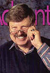
Remote volume and other controls
As I mentioned in the "PS" to Sound
Reproduction it is very important to have playback volume control at the listening place. Ideally, the
control has digital readout so that one can directly return to the preferred
setting once it has been found for a particular CD or LP.
To correct for occasional channel imbalances at the
listening position, it is nice to have a balance control handy.
Channel polarity switches are sometimes desirable. Recording techniques can be investigated by reversing the polarity of one channel. The audibility of absolute polarity is tested by
reversing both channels.
Finally, for a speaker like the PHOENIX that is flat on-axis and similar
in its power response, some recordings may sound bright because the microphone pickup was too close to the instruments. To correct for those situations I have found a frequency response downward tilt of 3 dB/decade to be a subtle, yet effective remedy. The tilt is also
beneficial when listening very close to the speaker in a small space, or when listening at lower
volume levels.
A tilt control can be added to the crossover/eq by adding
circuitry to the buffer stage that drives the three filter channels ( 3db_buff.gif
).
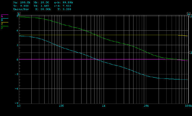
The response of the tilt circuit is given by the top two
curves of the 3db_oct1.jpg graph
with the toggle switch set to on and off.
One way to obtain remote volume control is to build a
separately housed preamplifier which is connected via cable to the crossover/eq. All the desired control functions can be assembled into a small package for convenient adjustment from the listening place. A circuit
for this is shown in preamp1.gif, gain-adj.gif.
It
combines volume, balance, mono-stereo switching, polarity and tilt control functions. The frequency response of the tilt control is given by the lower two
curves of 3db_oct1.jpg
. The umbilical cord between preamplifier and crossover/eq consists of four coaxial cables for left and right channel inputs and outputs, and
two wires with shield for the +/-15 V supply and ground.
If you wanted to experiment with a -3 dB/decade tilt
control, then you could first build a passive version of it and use it in your existing
system. 3db_oct2.gif
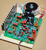
For many years I have used my own 8-channel power
amplifier, which was designed around single National Semiconductor LM12 power
opamps of 40 W per channel,
for a system similar to the PHOENIX. Today one might select the LM3886
, selling for $9 each. A printed circuit board is not needed for the heat sink mounted power
opamps,
because the few additional components can be wired point to point using terminal
strips and a copper plane for signal ground ( 3886amp.gif
). The voice coil presents a very easy load to the amplifier and there
is no risk of high frequency oscillation due to capacitive loading. Use one
opamp per driver. I have not found it necessary to provide speaker protection
and drive even the tweeter from a full bandwidth power amplifier.
If you want greater voltage or current capability, then use
opamps in bridged or paralleled configuration. Bridging two devices doubles the
voltage swing, but does not increase the maximum output current capability. It
is useful for higher impedance loads. Paralleling two devices doubles the
maximum output current, but keeps the same voltage swing. It is useful for
driving low impedance loads. Several opamps can be paralleled to increase
current capability n-times. A 200
W amplifier can be built with two paralleled LM3886 in each leg of a bridge
configuration. Check out the new LM4780
dual power amplifier. It has two 60 W amplifiers in one package which gives
close thermal tracking, important when bridging or paralleling amplifiers.
The power supply for the multiple operational amplifiers needs to be able to
supply large amounts of instantaneous current which requires a low impedance
transformer and large filter capacitors. ( 3886pwr.gif
)
Alternatively, you might consider a
battery supply, where the batteries are trickle charged. The power supply constitutes the major
cost for this type of DIY amplifier solution.
More power than 40 W per channel is desirable, because it tends to impart a
greater sense of ease to
the sound when playing back at high volume levels. Amplifiers that I have used with my speaker designs,
and that performed extremely well, were made by
Hafler (models DH-220 and DH-200),
ATI (Amplifier Technologies Inc., models
AT1504, AT1506, AT1802, AT6012),
BEL (Brown Electronic
Lab, +1 408 259 8648 voice, model 1001),
Muse Electronics (model 160),
Jeff Rowland Design Group (models MC-6, Concentra, Monoblock 6).
For other options check out the following web sites
which have interesting power and preamplifier designs for the DIY audio enthusiast:
The Self Site - Doug Self
Borbely Audio - Erno Borbely
The Audio Pages - Rod Elliott, e.g.
single chip 50W/8ohm
power amplifier
While the woofer is best driven from a solid-state
amplifier, the main panel is well suited for low distortion, low power tube
amplifiers. The 8" drivers generate a SPL of 99 dB above 250 Hz at 1 W / 1
m, decreasing to 92 dB at 100 Hz. The lower tweeter power sensitivity of 87.5 dB
is still adequate, because of the generally low power demand of most program
material. (Design Models-I, FAQ16,
FAQ20)
In all cases, most important are
low output impedance (<0.4 ohm) and low distortion (<0.1%) of the
amplifier over a 5 Hz to 50 kHz frequency range.
| Build-Your-Own | Main Panel
| Dipole Woofer | Crossover/EQ
| Supplies |
| System Test | Design Models
| Prototypes | Active Filters
| Surround | FAQ |
| 