----- Experience in your own room the magical nature of stereo sound -----


What's new


LX - Store


BLACKLIST


Conversations
with Fitz


OPLUG
Forum


Basics

The Magic in 2-Channel Sound

Issues in speaker
design

Dipole models

Active filters

Amplifiers etc

Microphone

FAQ's

Loudspeakers

Crossovers

Room acoustics

Stereo Recording and Rendering

Audio production

Conclusions


Projects

Your own desig

LXmini

LXmini+2

LXstudio

LX521.4

LX521
reference

ORION
challenge

ORION-3.4

PLUTO-2.1

WATSON-SEL

PLUTO+
subwoofer

THOR
subwoofer

PHOENIX
dipole speaker

Three-Box active
system (1978)

Reference
earphones

Surround
sound

Loudspeaker
& Room


Resources

Publications

Sound recordings

Links

Other designs

My current setup

About me

Site map


HOME


------------------
Digital Photo
Processes


------------------
The
Sea Ranch


------------------
My Daughter
the Jeweler


What's new


LX - Store


Conversations
with Fitz


OPLUG
Forum


Supplemental Information
ORION-3.3/3.4 new pcb

NOTICE - All material is copyrighted and for the personal, non-commercial use by the person who bought it from LINKWITZ LAB. It may not be passed on in any form for use by others. | Terms & Conditions | 


A - Circuit schematic for v3.3 and v3.4
B - Component placement
C - Material list
D - Input-to-output frequency response
E - Spot frequency response test tables
F - Midrange driver mounting
G - Woofer driver mounting in v3.4
H - Revisions
I - Experimenter's Corner

When correctly assembled the frequency response of the new pcb closely matches that of the original pcb for ORION-3.3.1. 

 
ORION-3.3 prototype circuit under test


A - Circuit schematic


For ORION-3.4 change the following resistor values:
U10B stage:  R60 = 4.22k & R63 = 7.5k
U11B stage:  R302 = 21.5k & R304 = 16.2k & R306 = 61.9k

Top


B - Component placement


U5A stage R and C labels, which are not to be loaded with components
R201, 202, 203, 204, 205, 206
C201, 203, 205, 206
Top


C - Material lists

material list33-O4pcb-102211.xls 
material list34-O4pcb-102211.xls

Parts supply sources: DigiKey, Mouser, Newark, Allied, Jameco, Farnell, CALRAD, ZACK  and others.

Capacitor availability search at Mouser

Capacitor availability search at DigiKey

Agilent Technologies makes a U1701B Handheld Capacitance Meter ($158) for selecting capacitors to 2% or tighter tolerances. 


D - Input-to-output frequency response


Top


E - Spot frequency response test tables

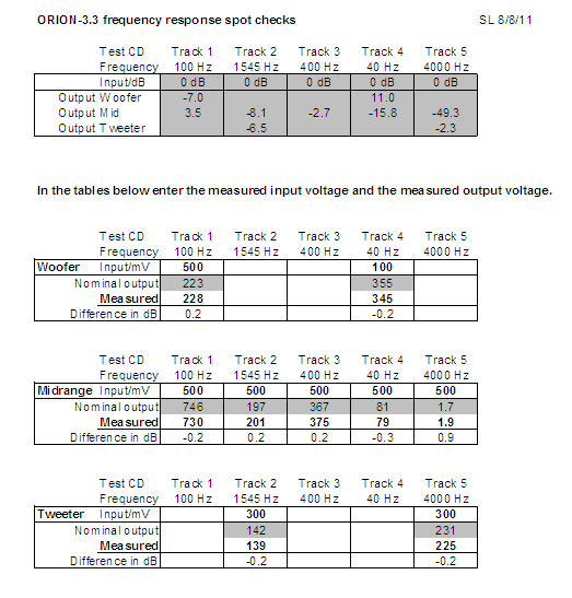
The tables on the left use the 5 test frequencies of the ORION Test CD. The measured voltages are examples and ideally should not deviate by more than 0.2 dB from the nominal values.

The nominal values in dB of the top table were measured on my new  ORION-3.3 pcb and compare closely to the values of the original pcb that I have had in use for a long time.

I measured the response using ARTA and an E-MU Tracker Pre. The calibration for 0 dB was done with the Tracker Pre output loaded by the 10.2 kohm input impedance of the circuit. 

Use the Response Spot Check spreadsheet to record your measurements and to calculate the deviation from nominal in dB. If you have a signal source other than the Test CD, then you can use the tables for 8 spot frequencies.


Top


F - Midrange driver mounting

Revision 1/19/06 of the ORION Construction Kit Documentation describes an obsolete mounting scheme for the midrange driver, by screwing it directly to the midrange and tweeter baffle A. Instead, the midrange driver should be held by the magnet. See https://www.linkwitzlab.com/orion-rev1.htm . While it is not absolutely necessary to use this different mounting scheme to obtain good sound, it should be noted that all development work for ORION-3.3 was done with a magnet mounted midrange. I cannot say what is lost without magnet mounting, since I never reverted back to panel mounting in the evolution of these loudspeakers. A midrange driver mounting kit is available from Wood Artistry.

G - Woofer driver mounting in v3.4

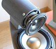
The SEAS L26RO4Y D1004-04 woofer has a larger magnet structure and greater excursion capability than the Peerless XLS 830452. To take advantage of this requires a higher power amplifier than the AT6012 such as the AT1806. Also, the bottom woofer's magnet would protrude past the grill cloth unless it is mounted with a wooden spacer Q of at least 5/8 inch (16 mm) thickness.  The outline of part Q is a 12 x 11.5 inch rectangle with a centric through-hole of 240mm diameter. The 11.5 inch width must have 2 x 3/4 inch cut-outs at the two bottom corners to clear parts J. 


H - Revisions

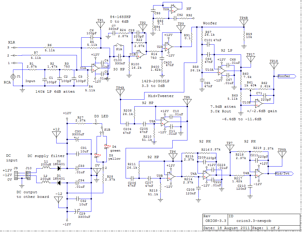
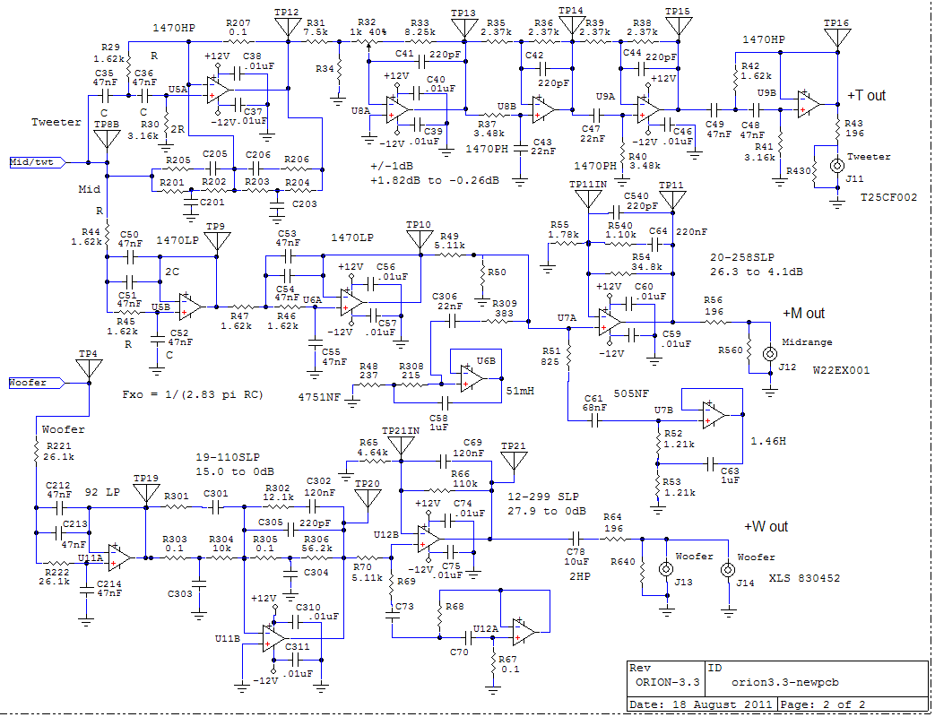
20 July 2015 - R66 in the U12B stage should be 110k if the SEAS L26RO4Y woofers are used. It should be 68.1k if the original Peerless XLS 830452 woofers are used. The circuit diagram above and the material list show the incorrect value.

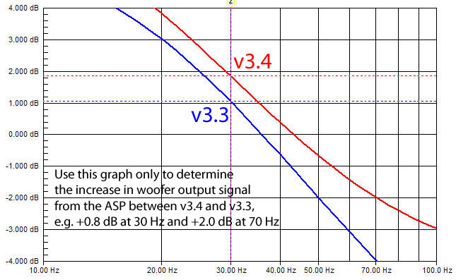
5 October 2011 - Added graph to read woofer drive difference between v3.4 and v3.3

3 October 2011 - Added Orion-3.4 information to circuit schematic, material list and G.

5 September 2011 - Added gold plated RCA to material list

18 August 2011 - Material list completed

11 August 2011 - First posting of Supplemental Information 
The new material list is under construction. Finish target: 19 August 2011.


I - Experimenter's Corner

Top

--------------------------------------------------------------------------------


What you hear is not the air pressure variation in itself 
but what has drawn your attention
in the streams of superimposed air pressure variations 
at your eardrums

An acoustic event has dimensions of Time, Tone, Loudness and Space
Have they been recorded and rendered sensibly?

___________________________________________________________
Last revised: 02/15/2023   -  © 1999-2019 LINKWITZ LAB, All Rights Reserved