
|
|
|
ORION supportHere you will find updates and new information for building your ORION speakers and for obtaining the best performance from them. Note: All material is copyrighted and for the personal, non-commercial use by the person who bought it from LINKWITZ LAB. It may not be passed on in any form for use by others. | Terms & Conditions | Please understand that I do not have the time to help you individually. Study my website and contact the OPLUG forum if you get stuck. Access to the Resource pages of the
ORION/PLUTO/LX User Group (OPLUG) After you have registered, please forward proof of
purchase to the OPLUG administrator: orionusers@gmail.com.
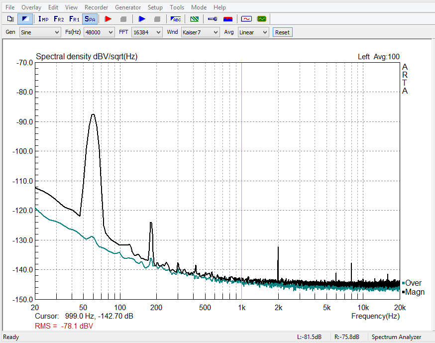
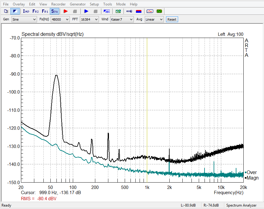
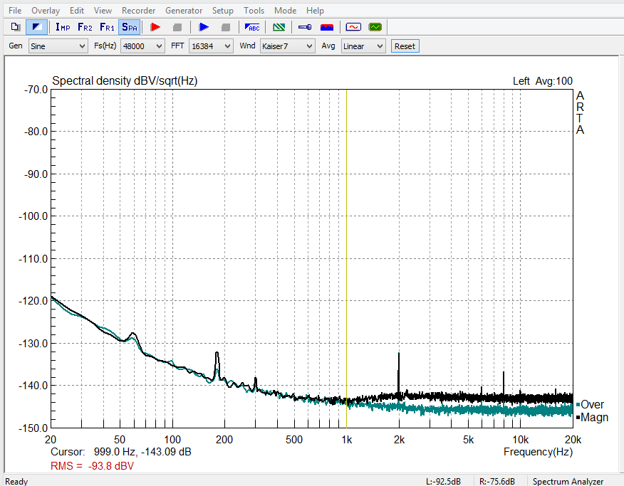
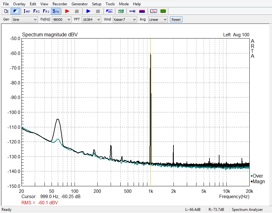
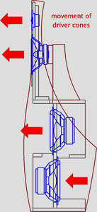
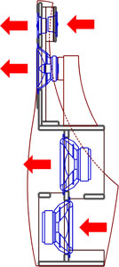
The admin will then grant you unrestricted access to all site content. ====================================== orion33_newpcb.htm orion35_newpcb.htm ====================================== ====================================== Here are ARTA impulse response data (*.pir) from my ORION-3.3 ASP TP2B - Woofer- Woofer cut - Mid - Tweeter Here are measured noise voltages for woofer, mid and tweeter outputs from my ORION-3.3 ASP. The voltages are displayed in dBV/sqrt(Hz), i.e. relative to 1 Vrms of noise in a 1 Hz bandwidth. Thus -140 dB/sqrt(Hz) corresponds to 100 nV per 1 Hz bandwidth, or to -97 dBV (14 uVrms) in a 20 kHz bandwidth. Normal hearing has the highest sensitivity around 3 kHz (Fletcher-Munson curves). The blue bottom curve is the noise floor of my E-MU Tracker-Pre sound card with shorted input. Visible are also 60 Hz power line and harmonics plus some spurious signals (probably my laptop) in the kHz range. It is important to chose a Kaiser window to separate the continuous signals from the random noise. I checked the accuracy of the measurement with calibrated noise and sine signals from the NTI Minirator MR1. ====================================== On this page I share with you some investigations that Don Barringer and myself are pursuing. You might want to experiment along those lines yourself and to give us feedback. In such case send me an email describing your observations. ====================================== Version 3.5 uses four of the SEAS L26RO4Y D1004-04 woofers
in a W-frame configuration that fits exactly into the space of the current
H-frame.
Cabinet drawing and cabinet parts list.
====================================== The SEAS L26RO4Y D1004-04 woofer has a larger magnet structure and greater excursion capability than the Peerless XLS 830452. To benefit from this requires an amplifier with higher power than the AT6012 such as the AT1806. Also, the bottom woofer's magnet would protrude past the grill cloth unless it is mounted with a wooden spacer Q of at least 5/8 inch (16 mm) thickness. The outline of part Q is a 12 x 11.5 inch rectangle with a centric through-hole of 240mm diameter. The 11.5 inch width must have 2 x 3/4 inch cut-outs at the two bottom corners to clear parts J. For ORION-3.4 change the following resistor values on the
old or new pcb: On the PHOENIX pcb change:
====================================== Page
1 and Page 2 of
the circuit diagram for update (59) when using the original pcb (Rev.120103
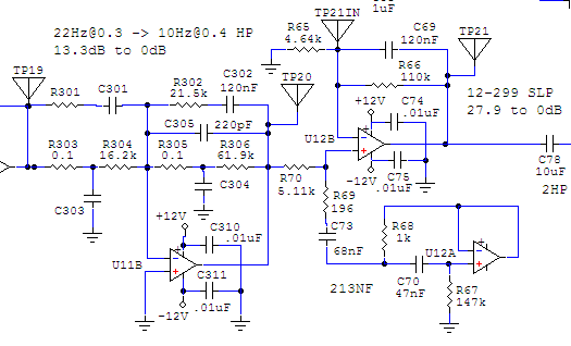
orion-2). ====================================== There has been some further refinement of capacitor values for v3.3: U7B stage: U1A stage See
(63) U3A stage Unchanged from (57) below: Agilent Technologies makes a U1701B Handheld Capacitance Meter ($158) that was used to
measure the optimum values, The material list has been updated by BrianL.: orion331_BOM_2011-06-09.xls ====================================== After hearing ORION-4 at AXPONA in Atlanta for the first time and noting the differences to his ORION-3.2.1 Don Barringer went home, lowered the midrange crossover frequency to 92Hz and reduced the output at the top end of the midrange driver slightly. The sound now matches ORION-4 closely, except for some of the articulation and dynamism that the new SEAS woofers deliver. When these new drivers become available, I will try them in the H-frame and publish here the necessary ASP and cabinet changes. U2A, U2B, U9A, U11A stages: U7B stage: U1A stage ORION-3.3 circuit diagrams for ASP pcb: Page 1, Page 2, component
layout and
ASP frequency response. The material list has been updated with the help of BrianL, DpB and others competent to give inputs. Thanks for your help. orion33_BOM_2011-06-03.xls Don and I highly recommend that you make these changes to your ORION-3.2.1 ASP, but neither of us nor Wood Artistry can provide an upgrade service at this time. NOTE: When used with THOR the increased phase-shift from the 92Hz crossover will influence the integration of the woofer with ORION-3.3. See https://www.linkwitzlab.com/frontiers_5.htm . For the Phoenix-MT1 pcb version of the ASP: MT1- U4A, U2A, U2B stages: Ph - U9A, U10A stages: Ph - U1A stage ORION-3.3 circuit diagrams for Phoenix-MT1 pcb: Page 1, Page 2 (both corrected 12/30/11) and
ASP frequency response. ====================================== If the output impedance of your preamp is greater than 200
ohm, then do not install the R400-C400 1.8kHz shelving lowpass filter. R22 = 1.96k The gain in each ASP channel will increase by 3.3 dB as a
consequence, but that should not be of concern. ====================================== Change C7 from 330nF to 390nF (or 330nF in parallel with
56nF) Customers who paid for an upgrade to Rev. 3.2 can obtain this latest revision from Wood Artistry for $20 plus S&H. The change for item (55) below will be included, but could be less desirable for warped vinyl playback. Please indicate your preference. ====================================== Reducing the S1 switched cut-off frequency of the 50Hz highpass filter to 30Hz extends the useful low frequency response, while still being effective in reducing subsonic cone displacements of the woofer drivers. It allows for higher volume levels with little loss at the low end. It is a useful mode for some recordings that cannot be played adequately loud otherwise. If C100 = 150 nF, change R100 from 21.5k to 34.8k ====================================== The required components are listed on the Revision 3 Materials and System Tune-up page. The circuit conversion takes 3 to 4 hours of soldering and testing. The system tune-up is likely to take considerably longer, but is necessary to hear all the benefits of this revision. I am aware of and frustrated by the shortage of 2% tolerance and low loss capacitors. Don Barringer has been trying to find new suppliers for the parts he needs. We know that useable parts are still being being manufactured in the US and Taiwan and probably in China in large quantities, but they are not handled by the known distributors for small quantities. The tolerance is important, the loss factor and film material are much less so, because the capacitors are often in series with large resistors. Other than the parts availability issue it should not be too difficult to modify the ASP since you already have the experience from building it yourself. If you did not build the xo/eq yourself and bought it from us, then contact Don Naples from Wood Artistry for a Return Material Authorization (RMA). Don has all the test equipment and experience. He worked in the electronics industry most of his life. Wood working used to be his hobby. But do not just send the xo/eq to him. He needs to schedule the upgrade according to his time and material availability and you may not want to be out of a working Orion for a long time. Right now he is gone fishing until August 1. Your cost for the upgrade service is $290 plus shipping and handling. Don can also work on DIY assembled crossovers, but this may result in additional charges. Ask for a quote If necessary, I will try to recruit others to help out. For pay of course. If you think that you are skilled and have the test equipment to perform a Revision 3 upgrade that would meet my quality standards, then send me an email. ====================================== There has been some concern that the ORION documentation has not been updated to the ORION+ to show the rear tweeter mounting and midrange driver mounting. The rear tweeter mounting is described on the ORION++ page. I would change the panel thickness from 3/8" to 3/4" to increase stiffness, thus to 11-3/8" x 6" x 3/4" and the two side supports to 6" x 1" x 3/4". Round or chamfer the corners as in the Wood Artistry example. The midrange driver mounting is described on the Revision 0.1 page. The key difference to the obsolete mounting bracket, where the magnet was glued to a wooden puck, is the use of a long screw through the center of the magnet, a replacement of the screw that holds the copper bullet of the driver, to attach the driver magnet to its wooden support. The Wood Artistry kit uses this technique. You could use the same approach in your own design of the mounting bracket. ====================================== Now that you are an ORION owner/builder you can request access to the locked areas of the forum. Sign in with your email and a password at https://oplug-support.org/index.php . You will be refused access but you can send an email to the Board Administrator (orionusers@gmail.com) from there and request to be admitted as an owner. ====================================== For polypropylene capacitor replacement use the Panasonic ECHS-Series of PPS film capacitors with 2% tolerance and 50 (or 100) WV DC rating. (e.g. 33nF = PS1H333G-ND) It appears that the ECSH series will be continued for some time. The increased dissipation factor of 0.3% for PPS compared to 0.1% for PP should have no sonic effect. For polyester film capacitor replacement use the Panasonic E-Series. (e.g. 10uF = E1106-ND) For updates and help also check in with the ORION/PLUTO Users Group ====================================== You may have missed the update to the ORION++ page a while ago. It was heavily based on inputs from John Stone. If you have concerns over the ORION's top end, then here is the way to experiment. Unfortunately the proper level setting is very critical and can be room dependent. ====================================== Updated material list to account for obsolete Panasonic capacitors, DIN connector and rear tweeters. ====================================== The new DigiKey part number for the 1kohm trimmer potentiometer is 3362P-1-102LF-ND ====================================== Here is the concept that should guide the experimental optimization of your ORION+/Room/Listener system setup: An electro-acoustic transducer needs to have a uniform (4p) power response and be flat on-axis under 4p/2p space conditions. Then it illuminates a room uniformly. This allows perceptual separation of the room sound from the direct sound. Room effects are minimized, if the room reflections arriving at the listener are delayed sufficiently, and if they replicate the direct sound sufficiently. ====================================== If you have any complaints about the high frequency response of the ORION+, then please consider the following: 1 - The ORION+ will reproduce what is on the recording and
what has been added to it in the signal path before the speaker driver terminals. But the
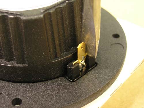
recording dominates. Have fun discovering what's in the ORION+. ====================================== Here are, after various iterations, the circuit and adjustment changes that resulted from the addition of the rear tweeter (Seas T25CF002, Millennium). a) The rear tweeter is wired in parallel to the front
tweeter and with opposite polarity. Both tweeters are driven at the same level. No series
resistor is used. (45b) 5/5/07 ====================================== 220pf ceramic caps are 1404PH-ND ======================================
====================================== In case you ever need to replace the voice coil assembly of your tweeter, here is the procedure for re-assembly: Before you fully tighten the front plate, apply a 2 volt sine signal at
500Hz. Push the front-plate to try to stop any distortion and tighten the
screw closest to this point first. (This low frequency allows large
excursions without much sound to better identify mechanical noises.) Laboratory Technician SEAS, Norway If you do not have a 500 Hz sine wave, then download 500Hz-sine.zip , unzip it and burn the file to CD. It will give you a 5 minute track of 500 Hz in normal stereo format. You can also download and install on your computer a virtual Minirator MR1 signal generator. Note the O ring on the outside of the plastic assembly. This must be
transferred from the defective vc to the new one. It provides an air seal. ====================================== When the Test Table on page 28 of the 1/19/06 documentation was updated, I missed to change the value for Track 3, Mid out, from 0.68 V to 0.77 V. ====================================== A pdf copy of the full size Side Panel drawing was provided by Eric Snyder to make the construction of the template easier. ======================================
====================================== A substitute for the OPA2134 operational amplifier is the OPA2604. You could also use the TL072 until either one of them is available. I would be curious to know if you hear a difference. ====================================== ORION Revision 0.1v4, magnet mounting From the inception of the ORION, several subtle equalization changes have been made to address the complicated interaction between the front and rear radiation from the midrange driver in the frequency region where symmetry is lost due to the concave driver cone on the front side of the baffle and the basket/spider/magnet structure on the back side of the baffle. The 400 NF notch filter and the 30-400 SLP dipole correction are instrumental for the on-axis frequency response. Further investigation since (36) has led to a change of the earlier (R51 + R307) value. It should be noted, though, that all these changes are of a magnitude where it becomes difficult to guarantee that they are optimum in an absolute sense. The components in the crossover/equalizer have finite tolerances and especially the midrange driver has variation in sensitivity, and to a lesser degree in frequency response shape, all of which can easily be of the size of the tuning adjustments being made here. Thus these updates should not be viewed as absolute and necessary for continued satisfaction. They are posted to signify a change in current production, giving current owners the option to either modify their systems as well or simply continue their present enjoyment without them. In any case, before modifying your electronics you should be quite certain that the woofer and tweeter level settings are optimum for your situation. They have much larger influence on the overall sound than these revisions. A 0.5 dB change in either level setting is quite significant to long-term listening enjoyment, even if the change is not immediately recognizable. Driver sensitivity can easily vary by 0.5 dB between different production units, but it can also be easily compensated in an active system like the ORION. For magnet or rim mount of the midrange driver: Notch filter (400 NF) resistors for magnet mount: Notch filter (400 NF) resistors for rim mount: ====================================== ORION Revision 0.1v3, magnet mounting After extensive listening and experimentation Don Barringer recommends the following: Change R307 from 196 ohm to 422 ohm to obtain R51+ R307 = 4.64k Confirm that: The assembled crossover/equalizer will be shipped with the changed R51+ R307 component value from now on. For the rim mounted midrange there is no change
from: ======================================= The test table on page 28 of the ORION Construction Kit Documentation has been updated to capture the frequency response changes that were caused by Revision 0.1 v2. The table goes with the material list component values under (33) and represents current shipment practice for the assembled xo/eq regardless of whether the Conversion Kit has been installed or not. Here is the current Test Table: 7-circuit test.xls The resolution of the frequency response graph on page 27 is not sufficient to show the changes. ====================================== The 8-pin IC socket Assmann A08-LC-TTA08-LC-TT or
Digi-Key part AE8908-ND is no longer available. ====================================== The material list on page 21 is missing in some printings of the ORION Construction Kit Documentation Here is the current list: 5-Orion-material.xls Install the Excel 97/2000 Viewer on your computer, if you do not have access to the Microsoft Excel spreadsheet program. ====================================== New DigiKey part numbers 100 pF is now P4570-ND ====================================== Assembly instructions for the Wood Artistry flat-pack and for mounting the midrange driver according to Revision 0.1 when using the Wood Artistry Conversion Kit 1A. ====================================== On page 10 of the 6/16/05 documentation in the 4th
paragraph: ====================================== You can download the ORION label file and print it out on premium photo paper. You might like to glue a 2" wide label to the front panel of your crossover/equalizer and a 4" wide label on top of the speaker's woofer baffle to help me promote the speakers.
====================================== Final cabinet assembly (page 4) 3M, Scotch Brand adhesive transfer tape 468MP is available on a 1" wide x 60 yard roll ====================================== No components are loaded on the ORION printed circuit board in the following locations: R24, R34, R50, R68, R69, R301 These are place holders for different circuit applications. ====================================== ORION Revision 0.1v2, magnet mounting Some further small changes were made to the midrange driver equalization which supercede (20) below. They add a little more warmth in the region below 400 Hz.
A - On the ORION circuit board in the 400 NF section check that R51 + R307 =
4.42k, i.e. R51 = 4.22k, R307 = 196 ohm, or R51 = 4.42k, R307 = 0 ohm jumper.
Check that C61 = 39nF. Change C62 from 4.7nF to 3.3nF. B - If the PHOENIX circuit board is used, then change R51 to 4.42k, change C61 to 39nF and add/change C62 = 3.3nF in the 400 NF section. In the 30-400 SLP section change R55 from 3.48k to 3.16k and change R54 from 42.2k to 38.3k. These changes are not necessarily related to the magnet mounting and might be tried without it. ======================================= Crossover/Equalizer power consumption Each operational amplifier could draw 5 mA max of quiescent current. Allocate 10 mA per OPA2134 package plus 50% margin for a total of 15 mA/package. Thus, the power supply for 22 ICs should be capable of 330 mA. Average power consumption is about 5 W when using +/-12V. Do not exceed +/-18V. ====================================== Side panel material The side panels do not need to be constructed out of multi-layer plywood. A variety of materials can be used, but they should not ring for lack of internal damping when knocked on. The panel thickness should be 3/4 inch to 1 inch maximum to maintain the desired acoustic path length from the rear of the midrange driver to the front, and to maintain the distance from the tweeter to the cabinet edge. See also (8) below. ====================================== The McFeely screws are now available over the web: ======================================= Digi-Key Finland (https://fi.digikey.com/)
might be a good source for electronic parts in Finland. They use the same part
numbers as in the ORION material list. ====================================== Revision 1/26/04 of the Construction Kit
Documentation. ====================================== ORION Revision 0.1, magnet mounting, requires a small change to the 400
Hz notch filter to bring up the response by about 0.5 dB. ====================================== For ORION cabinet work in the US contact Wood Artistry ====================================== For ORION cabinet work in Australia contact Steven Rosenberg ====================================== For ORION cabinet work in the UK there is no longer a contact. ====================================== Side panel drawing templates have been provided by Alister Sibbald: US
Letter format The PDF files print out on multiple pieces of paper,
making it necessary to match each piece with the next, which is the
purpose of the "crosshair" markings in each corner of each sheet. It
makes things much easier if they are printed out on the most transparent paper
available. If Transparency sheet is available, that is ideal, as it makes
matching up the crosshairs extremely simple. Once you have taped up all the
pages with Scotch tape, the resulting full size pattern can be glued to your
template and used to cut it out. See also the side panel drawing (9) below. ====================================== Revision 1/26/04 documentation for the new ORION-ASP pcb. On page 10, 2nd paragraph, it should read correctly: On page 4, Final cabinet assembly, add the underlined: ====================================== Adjusting the gain of the 3 crossover channels The tweeter and woofer channels have trim potentiometers (R32, R61) to adjust the gain by +/-2.5 dB. This is a large range in order accommodate normal manufacturing variations in driver sensitivity, in the order of 0.5 dB, and differences in room acoustics and listener preferences. The normal position of the potentiometer is at the center of the tick mark range. The gain changes 0.5 dB between adjacent tick marks. The XO/EQ was designed for power amplifier voltage gains between 24 dB and 28 dB. Amplifiers with higher gain degrade noise and hum rejection. All three (four, if woofers are driven individually) amplifiers should be identical. If power amplifiers of different voltage gain are used, then the potentiometers may have insufficient range and attenuators must be added to the output of the XO/EQ. The lowest gain amplifier determines by how much the input signal to the other amplifiers has to be attenuated. The 196 ohm output resistors (R43, 56, 64) must be replaced as necessary by a resistor R1. A resistor R2 must be soldered between the RCA output connector and nearby circuit ground. Determine the values of R1 and R2 from attnrout.gif by setting Rout = 2k ohm. For example, a 5 dB attenuator (a=0.56) would have R1 = 3.56k and R2 = 4.56k. If the input impedance of the higher gain power amplifier is 10k, then the actual attenuation will be 20 log( (4.56//10)/(3.56 + 4.56//10) ) = -6.6 dB, which is higher than targeted. Thus R1 needs to be reduced and a modified R2' = 4.56//10 = 3.13k used in the formula for R1 = R2'(1-a)/a = 2.44k. Choose the next closest standard value resistors. ======================================== Reducing "Hum" With many components connected to the power line there is the potential of
"ground loops" which induce hum into the system. Ground loops are
closed circuits which provide paths for low level AC ground currents to flow
between different ground connections, if these connections are at different
ground potentials, or if magnetic stray fields from power transformers induce
currents into the loops. If the RCA cables which interconnect the different
pieces of equipment are part of the loops, then the ground currents will also
flow in the cable shields. Cable shields and associated RCA connector junctions
have a finite ohmic resistance so that there is a voltage drop induced across
that resistance by the ground current. A "hum" voltage is thereby
added to the normal signal voltage.
The AT6012, for example, is a very quiet power amplifier. I measure less than -80 dBV (<100 uVrms) hum and noise across its output binding posts with the RCA inputs short-circuited. The measurement is performed with a NTI Minilyzer ML1, which has balanced inputs. When there has been a hum problem in any of my systems, it was never due to one of the different ATI power amplifiers that I have used over the years. See also ORION FAQ10. ====================================== Spaekon connectors Note, the following alternative is not recommended when building the speakers yourself, because of potentially lower reliability of connections due to increased difficulty in assembly. These parts are used on the custom assembled ORION System to simplify the speaker setup for the user. There is no sonic benefit over the solution in the Construction Plans+. Instead of soldering the speaker cable to a solder terminal strip at the speaker end we install a Neutrik 8-pole Speakon connection. The part numbers in the Mouser catalog are: 568-NL8MPR-BAG male, chassis, Faston tabs, $7.28 For a Belden 8-conductor cable 1811A we make the following connections to minimize crosstalk: Tweeter: blk-wht ====================================== Revision 4/18/2003 documentation Page 27, CD track 2, Tweeter out = 0.42 +/- 0.02, not 0.40 +/- 0.02 C62 = open, not 12 nF Material list and loading chart ====================================== If Digi-Key is out of stock on a certain part, ask for an alternate part with the same value and tolerance. Voltage and Wattage ratings are not critical. I like to order over the phone to make immediate adjustments (1-800-344-4539). For example, the Yageo 3.48K, 1% resistor (3.48kXBK) can be replaced by a BC Components resistor (BC3.48KYCT). Another good source for parts is Mouser. ====================================== Side panel drawing
with curve radii. ===================================== Any material can be used for the side panels, plywood, MDF, solid wood, Plexiglass, Corean etc. as long as it is sturdy. The edges can be rounded or beveled. None of this has an effect on the sound as long as the outline of the side panel remains unchanged and it is firmly attached to the internal frame. ====================================== Revision 10/16/02 documentation updates: Page 4 Page 9 Page 15 Page 17 Page 20 Page 21 Page 26 ======================================
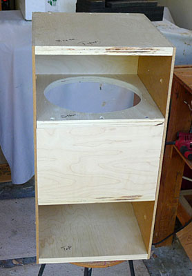
====================================== Material list and loading chart Install the Excel 97/2000 Viewer on your computer, if you do not have access to the Microsoft Excel spreadsheet program. ====================================== Revision 10/14/02 documentation - Correct page 21 - Page 18 ====================================== Before Revision 10/14/02 documentations - Page 5 - Page 14 - Page 11, 17, 18, 19, 20 ====================================== The Orion design was frozen August 1, 2002. ====================================== Assembly of the ORION
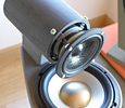
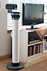
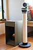
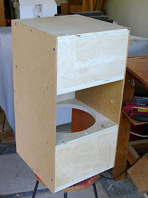
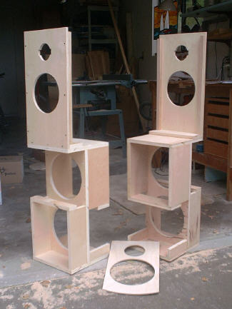
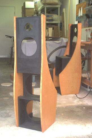
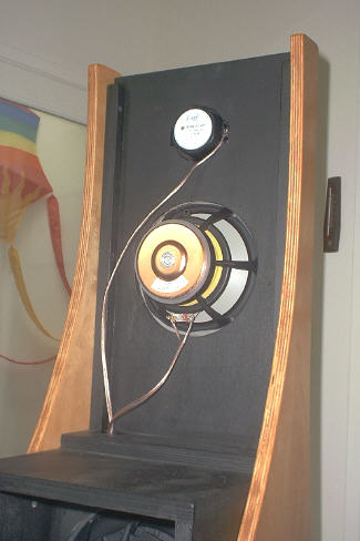
Front and rear view of the internal frame before it is painted flat black. The finished dress panel is glued to the top section of the frame later on.
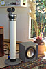
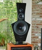
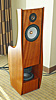
The side panels have been attached to the internal frame.
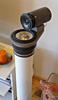
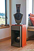
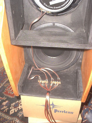
Rear of top panel.
Wiring of the 4 speaker cables to terminal strips inside the cabinet.
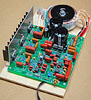
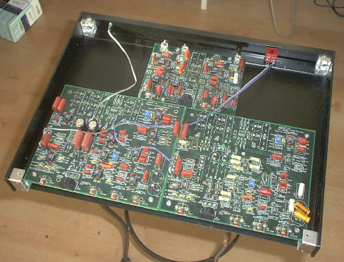
Crossover/Equalizer prototype.
|
|
| ||||


