|
|
|
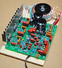
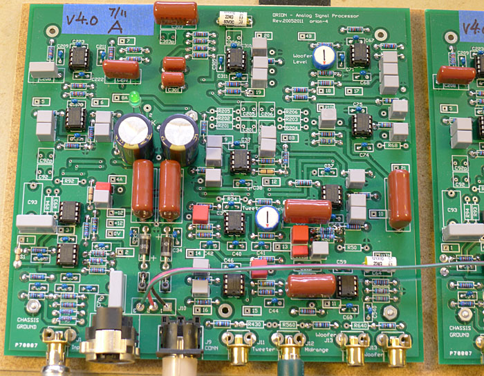
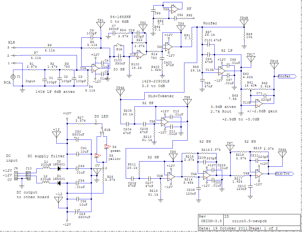
ORION-3.5N - All material is copyrighted and for the personal, non-commercial use by the person who bought it from LINKWITZ LAB. It may not be passed on in any form for use by others. | Terms & Conditions | PCB Rev. 03072011 orion-4 A - Circuit schematic
When correctly assembled the frequency response of the new pcb closely matches that of the original pcb for ORION-4.
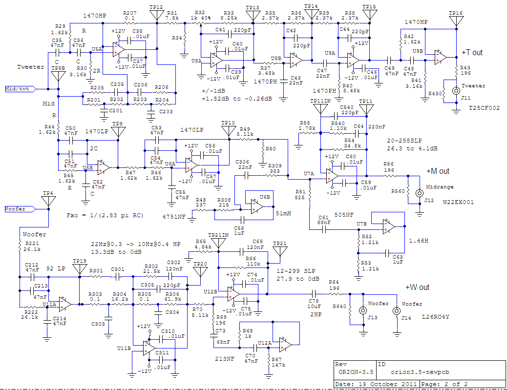
A - Circuit schematic
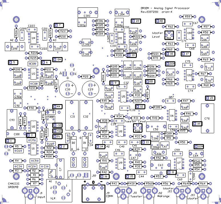
B - Component placement
U5A stage R and C labels, which are
not to be loaded with components
C - Material listmaterial list35-O4pcb-102211.xls Parts supply sources: DigiKey, Mouser, Newark, Allied, Jameco, Farnell, CALRAD, ZACK and others. Capacitor availability search at Mouser Capacitor availability search at DigiKey Agilent Technologies makes a U1701B Handheld Capacitance Meter ($158) for selecting capacitors to 2% or tighter tolerances.
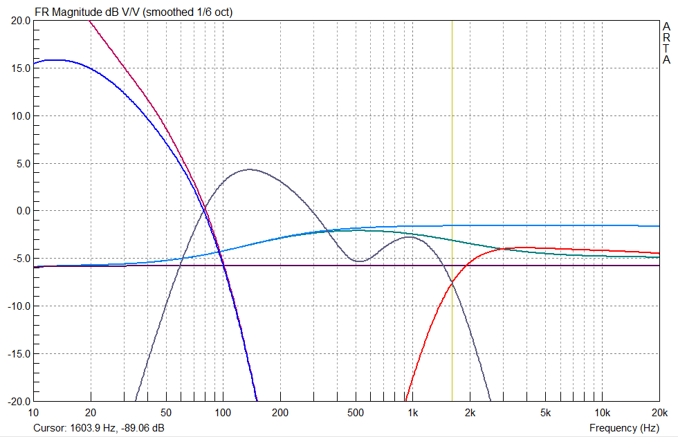
D - Input-to-output frequency response |
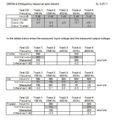 |
The tables on the left use
the 5 test frequencies of the ORION Test CD. The measured voltages are
examples and ideally should not deviate by more than 0.2 dB from the
nominal values.
The nominal values in dB of the top table were measured for the new ORION-4.0 pcb. I measured the response using ARTA and an E-MU Tracker Pre. The calibration for 0 dB was done with the Tracker Pre output loaded by the 10.2 kohm input impedance of the circuit. Use the Response Spot Check spreadsheet to record your measurements and to calculate the deviation from nominal in dB. If you have a signal source other than the Test CD, then you can use the tables for 8 spot frequencies. |
 Front |
 Rear |
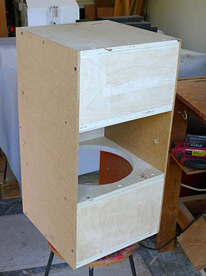
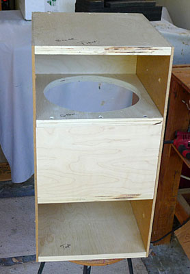
Example of a W-frame of
equal width and construction as required for ORION-3.5
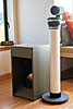
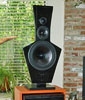
The difficulty with this design is in aligning the multiple wood panels so that the box is square in the end. I hold everything together with screws and pre-drill the holes. Adding glue makes for a slippery alignment unless you use fixtures. The two SEAS woofers are very massive and develop considerable forces, which must be absorbed by the cabinet. Using glue in addition to screws is desirable. Left and right curved dress panels are screwed from the inside to the 1/4 inch thick hardboard side panels. All other panels are made of 3/4 inch multi-layer plywood.
|
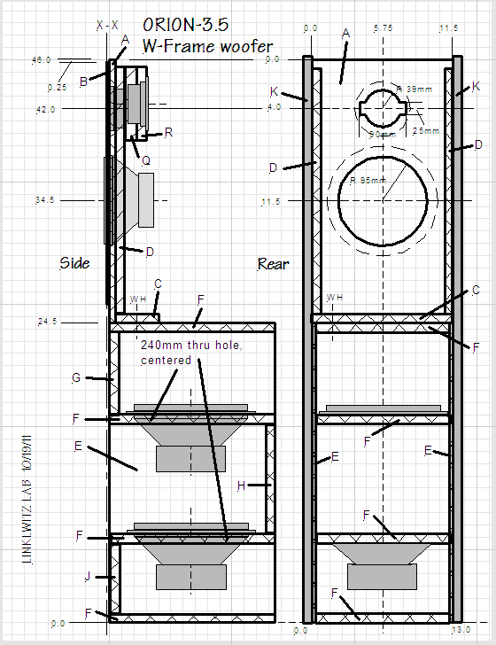 |
Parts List for the internal frame. Drawings for side and dress panels can be found in the paper documentation.
|
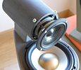
Midrange driver mounting
Revision 1/19/06 of the ORION Construction Kit
Documentation describes an obsolete mounting scheme for the midrange driver, by
screwing it directly to the midrange and tweeter baffle A. Instead, the midrange
driver should be held by the magnet. See https://www.linkwitzlab.com/orion-rev1.htm
. While it is not absolutely necessary to use this different mounting scheme to
obtain good sound, it should be noted that all development work for ORION-3.3
was done with a magnet mounted midrange. I cannot say what is lost without
magnet mounting, since I never reverted back to panel mounting in the evolution
of these loudspeakers. A midrange driver mounting kit is available from Wood Artistry.
Top
14 September 2012 - Note R22 was changed following the observations in the Experimenter's Corner below.
20 October 2011 - First posting of this page.
--------------------------------------------------------------------------------
|
| ||||