----- Experience in your own room the magical nature of stereo sound -----


What's new


LX - Store


BLACKLIST


Conversations
with Fitz


OPLUG
Forum


Basics

The Magic in 2-Channel Sound

Issues in speaker
design

Dipole models

Active filters

Amplifiers etc

Microphone

FAQ's

Loudspeakers

Crossovers

Room acoustics

Stereo Recording and Rendering

Audio production

Conclusions


Projects

Your own desig

LXmini

LXmini+2

LXstudio

LX521.4

LX521
reference

ORION
challenge

ORION-3.4

PLUTO-2.1

WATSON-SEL

PLUTO+
subwoofer

THOR
subwoofer

PHOENIX
dipole speaker

Three-Box active
system (1978)

Reference
earphones

Surround
sound

Loudspeaker
& Room


Resources

Publications

Sound recordings

Links

Other designs

My current setup

About me

Site map


HOME


------------------
Digital Photo
Processes


------------------
The
Sea Ranch


------------------
My Daughter
the Jeweler


What's new


LX - Store


Conversations
with Fitz


OPLUG
Forum


| Challenge | Requirements | Supplies | Promotion | Subwoofer | Photos | Reviews | ASP | FAQ | Revision 0.1 | Revision 2 | Revision 3 |


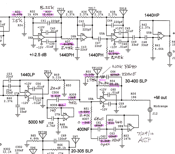
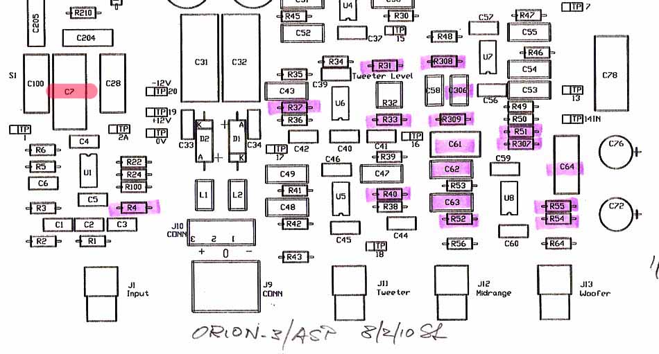
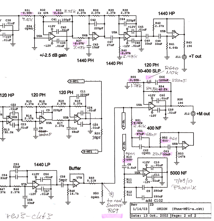
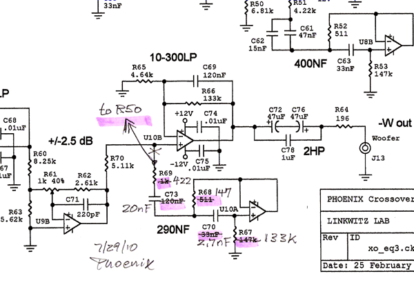
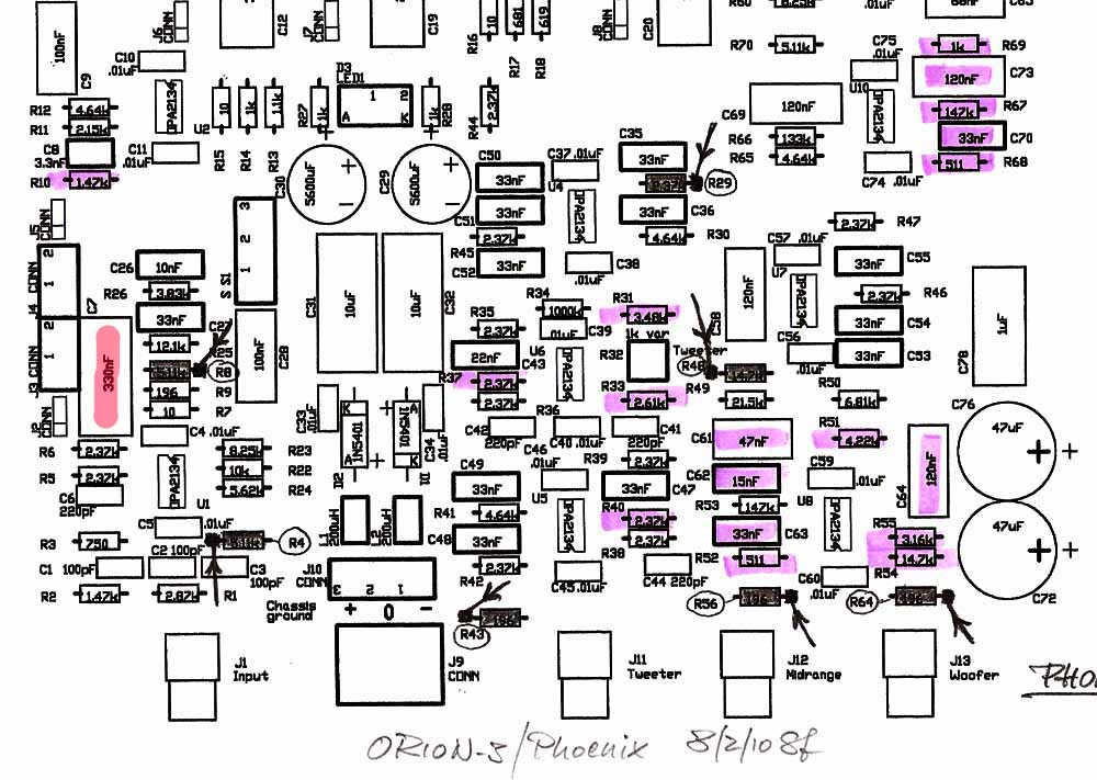
1 - Materials for Revision 3 

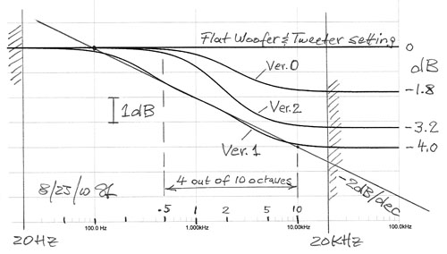
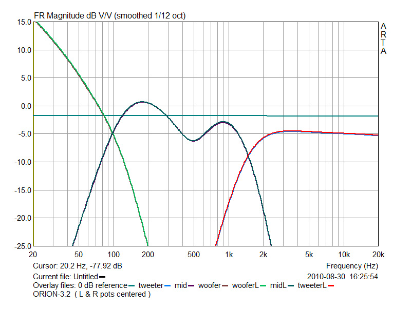
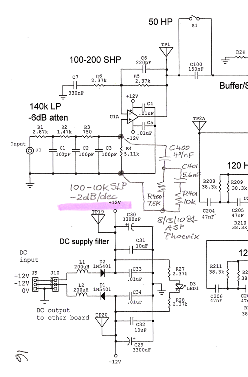
Last update, 8/31/10:  Frequency response tables for Rev. 3.2

8/12/10 Revision 3 is on hold. 
Items 6) and 7) are in question and more circuitry will be added to control the timbral color

8/13/10 Version 1 - I have tamed the Beast. It can go

8/23/10 Version 2 - The Beast has gained some body weight without losing agility

Frequency response equalization in Versions 0, 1 and 2 of Revision 3 as controlled by 6) below. 


Version 2 - 8/23/10

Resistors are 1/4W, metal film, 1% tolerance
Capacitors are 2% tolerance, with loss factor between 0.1% and 0.3%, >25V
Values in parenthesis (...) were used for ORION+.
[Digikey Part Number examples]


ASP printed circuit board

Circuit diagrams 
rev3-ckt1.png
rev3-ckt2.png
rev3-layout-ASP

1)  +/-1 dB Tweeter level adjustment (+/-2.5 dB)
R31 = 7.5k (3.48k)
R33 = 8.25k (2.61k)

2)  Tweeter delay, 1440PH
R37 = 3.48k (2.37k)
R40 = 3.48k (2.37k)

3)  Dipole EQ (30-400 SLP)
R55 = 1.78k (3.24k)
R54 = 34.8k (38.3k)

R-C series  network soldered between the eyelets of C64:
C64 = 220nF (120nF) in series with R640    [P3880-ND]
R640 = 1.10k

4)  Notch filter (400NF)
R51 = 2.61k (4.75k)
R307 = jumper (348ohm)
R52 = 464ohm (511ohm)
C61 = 68nF (39nF)    [P3868-ND]
C62 = open (3.3nF)
C63 = 22nF (33nF)    [P3856-ND]

5)  Notch filter (5000NF)
R309 = 422ohm (348ohm)
R308 = 147ohm (511ohm)
C306 = 20nF (5.6nF)    [16nF, P3853-ND and 4.3nF, P3839-ND in parallel, or 10nF//10nF, or 16//3.9, etc]

6)  Version 2:   1.8kHz, -3.3dB SLP
R-C series network soldered onto the eyelets of existing R4 (5.11k) of U1A:
R400 = 5.62k in series with C400  
C400 = 13nF  (12//1, 12//1.2, 10//3.3)  Match L and R channel capacitors

6)  Version 1:   100Hz to 10kHz, -2dB/dec SLP
First R-C series network soldered onto the eyelets of existing R4 (5.11k) of U1A:
R400 = 7.5k in series with C400  ( R400 connects to the grounded eyelet of R4)
C400 = 47nF    [PS1H473G-ND]   (C400 connects to the opamp side of R4 and to R400)
Second R-C series network soldered across R400:
R401 = 10k
C401 = 5.6nF  [PS1H562G-ND]

6)  Version 0:   2.3kHz, -1.8dB SLP
R-C series network soldered onto the eyelets of existing R4 (5.11k) of U1A:
R400 = 11.0k in series with C400  
C400 = 5.6nF 

7)  100-200 SHP
C7 = 330nF (330nF)   


PHOENIX & MT1 printed circuit board

Circuit diagrams 
rev3-ckt1.png
rev3-ckt3.png
rev3-ckt4.png 
rev3-layout-Phnx.jpg

1)  +/-1 dB Tweeter level adjustment (+/-2.5 dB)
R31 = 7.5k (3.48k)
R33 = 8.25k (2.61k)

2)  Tweeter delay, 1440PH
R37 = 3.48k (2.37k)
R40 = 3.48k (2.37k)

3)  Dipole EQ (30-400 SLP)
R55 = 1.78k (3.24k)
R54 = 34.8k (38.3k)

R-C series network soldered between the eyelets of C64:
C64 = 220nF (120nF) in series with R640    [P3880-ND]
R640 = 1.10k

4)  Notch filter (400NF)
R51 = 2.61k (4.75k)
R52 = 464ohm (511ohm)
C61 = 68nF (39nF)    [P3868-ND]
C62 = open (3.3nF)
C63 = 22nF (33nF)    [P3856-ND]

5)  Notch filter (5000NF)
R10 = open (100ohm)  Disconnects the existing 5000NF
R69 = 422ohm (open)   Insert one lead of R69 into the eyelet closest to the edge of the board. Connect the other lead of R69 to a 3.5 inch wire. Connect the other end of that wire to the eyelet of R50 (open) that connects with R49.  
R68 = 147ohm (open) 
R67 = 133k (open)
C70 = 2.7nF (open)
C73 = 20nF (open)    [16nF, P3853-ND and 4.3nF, P3839-ND in parallel, or 10nF//10nF, or 16//3.9, etc]

6)  Version 2:   1.8kHz, -3.3dB SLP
R-C series network soldered onto the eyelets of existing R4 (5.11k) of U1A:
R400 = 5.62k in series with C400  
C400 = 13nF  (12//1, 12//1.2, 10//3.3)  Match L and R channel capacitors

6)  Version 1:   100Hz to 10kHz, -2dB/dec SLP
First R-C series network soldered onto the eyelets of existing R4 (5.11k) of U1A:
R400 = 7.5k in series with C400  ( R400 connects to the grounded eyelet of R4)
C400 = 47nF    [PS1H473G-ND]   (C400 connects to the opamp side of R4 and to R400)
Second R-C series network soldered across R400:
R401 = 10k
C401 = 5.6nF  [PS1H562G-ND]

6)  Version 0:   2.3kHz, -1.8dB SLP
R-C series network soldered onto the eyelets of existing R4 (5.11k) of U1A:
R400 = 11.0k in series with C400  
C400 = 5.6nF 

7)  100-200 SHP
C7 = 330nF (330nF)


Reworking the pcb

Center the tweeter level potentiometer R32.

I remove a component by heating one of its two eyelet pads until the solder re-flows and quickly pulling out that lead wire with tweezers. Next the other component wire is pulled out by the same procedure. The hole in the eyelet is opened up by re-heating the solder and quickly inserting a wooden toothpick into the hole. Now both leads of a new component can be inserted into the holes, although sometimes only partially. A little heat will seat them down. I rework everything from the component side of the pcb and keep the leads short so that I do not have to clip them from the circuit side. 

If you have wires running underneath the pcb, then a heated component lead could melt through the wire insulation and cause a short as you insert the new component. So be careful not to punch through the insulation of the +/-12V and ground wires running between the boards.


Frequency response of the ASP


Measured frequency response of the crossover/equalizer for Revision 3.2 using ARTA software by Ivo Mateljan. 


Spot-check the output voltage Vout at different frequencies for a given input voltage Vin. For example from the graph:

Output Frequency dB Vout / Vin
Tweeter 10 kHz -3.13 0.70
Mid 1 kHz -1.56 0.84
Mid 500 Hz -4.53 0.59
Mid 200 Hz +2.19 1.29
Woofer 50 Hz +6.88 2.21

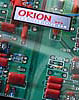
ORION Test CD frequencies (tracks):

Output Frequency (track) dB Vout / Vin
Tweeter 4 kHz (5) -2.81 0.72
Tweeter 1545 Hz (2) -6.25 0.49
Mid 1545 Hz (2)  -8.44 0.38
Mid 400 Hz (3)  -3.44 0.67
Mid 100 Hz (1)  -2.66 0.74
Woofer 100 Hz (1) -3.75 0.65
Woofer 40 Hz (4)  +9.69 3.05


2 - System Tune-up

Tips for balancing the ORION from Don Barringer

Check first, using pink noise from track 6 of the ORION Test CD, that left and right tweeters have the same output. Listen from about 1 m in front of each speaker, then bring up the level on the lower level tweeter. My hearing acuity for this test is very low, though Don reports that he could match his tweeters that way. I went with the assumption that both tweeters are very close because they came from the same batch rather than to trust my hearing for a match-up by this test. 

After you turn on Orion-3.1 for the first time and everything seems to be working properly, you must search for the right tweeter level setting. It is not necessarily in the center of the tweeter level potentiometer. Tweeter sensitivity varies, possibly up to 0.5 dB, even under the tight manufacturing process control that Seas has implemented. With Revision 3.1 a 0.2 dB change (1 hour of the 7 am to 5 pm range) in potentiometer setting can be significant, especially when you are close to the optimum setting. The optimum could be between 10 am and 12 noon or 2 pm and 4 pm, for example due to tweeter sensitivity differences. Nominal is the range from 11 am to 1 pm. To find the right setting takes time and is not necessarily accomplished in one or two listening sessions. This is especially true for the woofer level since there is so much variability between recordings. So when you have found the tweeter potentiometer setting that seems optimum, live with it for a few days. Then increase the level by 0.2 dB (1 hour) and listen. Do you want to go back to your previous setting?

The volume control on your preamp controls the size and distance of the Auditory Scene. I use recordings with voices and instruments, orchestral and in natural settings like: Ramirez, Misa Criolla, Jose Carreras, Philips 420 955-2, or Stravinsky, Histoire du Soldat, Chesky CD122. You may want to play at ever higher volume levels because you do not experience strain or fatigue. But the AS can become too large and out of proportion spatially and in overtones. At reduced volume levels, when everything sounds neutral and smooth, you may lose aliveness that can be had at realistic sound levels.

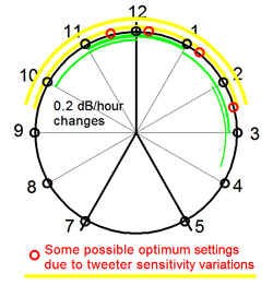
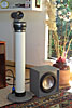
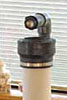
The tweeter potentiometer has a level setting sensitivity of 0.2 dB/hour and a range of +/-1.0 dB.

The woofer potentiometer has a level setting sensitivity of 0.5 dB/hour and a range of +/-2.5 dB.

A 0.5-inch diameter, though more costly, potentiometer provides better mechanical resolution and makes the adjustment setting easier to see. We use a Bourns Series 3345P potentiometer (DigiKey part number  3345P-102-ND). Tweeter and woofer levels increase counter-clockwise with this model.


Sometimes you may want to know the frequency of a sound. To match a pitch and find its frequency download the Virtual Piano from Mike Marzalek's "CI Theory" website.


| Challenge | Requirements | Supplies | Promotion | Subwoofer | Photos | Reviews | ASP | FAQ | Revision 0.1 | Revision 2 | Revision 3 |

CAUTION: The content of these pages may change without notice as I learn new things or find better descriptions. The designs presented here may change as I make new observations or gain more insight. I see myself as a seeker of truth, though I now know that every person is, and ultimately truth is a construct. There is only this. Maybe what has been done here points you to it. Audio has overwhelmingly been a hobby for me, for my own pleasure and love of music. I enjoy to share what I found and possibly to dispel a few misconceptions. My interest is not on the business side, though I like that my activities pay for my hobbies. You may not agree with some or all aspects of my designs, the approach that I take to them, or the theories. I have no problem with that. Just do not ask me "what would happen if ...". Changes that you make to the designs are for your own pleasure and at your own risk. But if you learn something worthwhile, then please let me know. I have received increasing amounts of email. I have responded to every legitimate letter that made its way through the Junk Mail, even when it meant repeating what has been published. There is an ORION/PLUTO Users Group with people who can help you. Go there first. I will still respond to every email, but you may get redirected. I consider my writings in these web pages as brief and to the point. I labor over every sentence and word and provide little redundancy. Read thoroughly and maybe more than once. I do not write for the rank beginner, but for those who have been around the block. You may need to study up. The links in my text are for that. You may find what seems like an inconsistency here and there. Look at the date of the page for when it was last updated. I am not going back over every page to bring everything on it up-to-date.  I have not been standing still since I started this web in 1999 and with the idea of a brain dump of my previous findings so they would not get lost to the audio community, and with the PHOENIX as an example, so you could test my findings for yourself. In 2006, I thought I would go into a support and maintenance mode. No new design. Stuff happened, more enjoyment to share. Be forewarned, I am sowing seeds of discontent. 


What you hear is not the air pressure variation in itself 
but what has drawn your attention
in the streams of superimposed air pressure variations 
at your eardrums

An acoustic event has dimensions of Time, Tone, Loudness and Space
Have they been recorded and rendered sensibly?

___________________________________________________________
Last revised: 02/15/2023   -  © 1999-2019 LINKWITZ LAB, All Rights Reserved