|
|
|
Recording & Rendering--- Recording
& Rendering 101 --- Acoustics vs.
Hearing
--- Subjective evaluation ---
Theory - Mapping from recording to playbackI will present some background information to better understand the function of the previously discussed 4-microphone array. It is important to know how the "view" from the microphones into the auditory scene at the recording venue is mapped into the "view" that a listener perceives in front of two loudspeakers in his listening room. The microphone array "sees" sound waves arriving from different angles with differing sensitivity. It does not have blind spots, just dimmer regions. It also has bright regions to the sides where all sounds over a wide range of arrival angles become mapped into either the left or the right loudspeaker with little coherence between them. I take the well known ORTF 2-microphone array as an example for mapping sound from the recording site to what is heard at the playback site.
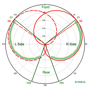
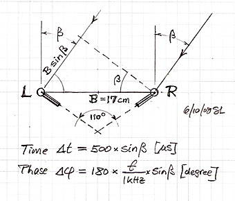
The ORTF microphone array uses two cardioid microphones. Each has a sensitivity to sound pressure that varies as r = 0.5 + 0.5 cos(a) with respect to the angle a from which sound arrives. The two microphones capsules are separated by 17 cm and are mounted with a 1100 angle between them. Thus their polar response curves have their maximum at +/-550. A sound wave arriving from 450 will produce an output of almost 1.0 from the Right microphone and about 0.6 from the Left microphone. When these two signals are applied to Left and Right loudspeakers, they will produce a phantom signal between the loudspeakers and towards the Right loudspeaker. The separation between the microphones has the effect that sound waves arriving at an angle b will reach one microphone sooner than the other due to the path length difference of (17 cm) x sin(b). With b = 450 the signal will arrive at the Right microphone 354 ms sooner than at the Left microphone. This will pull the phantom image even further towards the Right loudspeaker due to the Precedence Effect of auditory perception. For source angles from 510 to 1600 the combined effect of level and arrival time differences between the microphones will map all signals into the Right loudspeaker. Signals between 1600 and -1600 will be mapped again between Right and Left loudspeakers though they arrive from the rear of the microphone array. The 1020 front section in the polar diagram represents the "Stereo Recording Angle" SRA of the ORTF array. All signals within its range are mapped between Left and Right loudspeakers. The theory behind this mapping operation is explained on the Stereo recording angles page. Below is a "floor plan" of recording and playback situations to further illustrate the mapping operation.
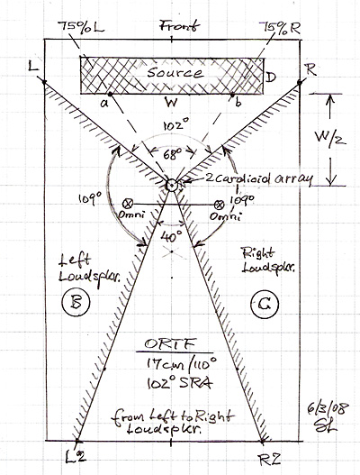
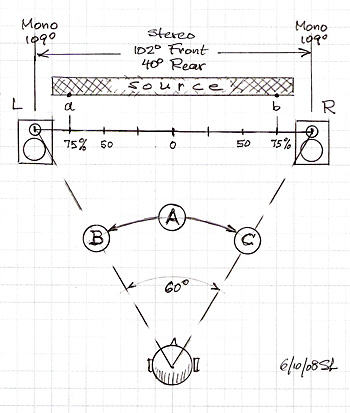
Presumably the microphone array is set up to capture the source, for example an orchestra, in front of it and also some of the hall reflections and reverberation that are part of the sonic scene and which would be experienced by a listener at the recording site. With the array positioned 1/2 source width W in front of the orchestra and the fixed stereo recording angle of 1020 the whole orchestra is mapped along the line between the Left and Right loudspeakers. The 75% points on this line correspond to an angle of 680 on the recording side. Sources from a to b within this angle are mapped between the 75% points in the playback room. Wide regions B and C to the left and right of the microphone array and over a 1090 angular sweep are mapped either into the Left or the Right loudspeaker as dual mono reverberation. No realistic phantom images can be created from these signals. It is not clear to me what the perceptual benefits of these signals might be and I strongly suspect that they give a false rendering of the recording venue since they only contain side reflections and reverberation and no direct signals from the orchestra.
It seems to me that the arrival time differences due to the 17 cm separation of the cardioids in the ORTF array are primarily effective above a 1 kHz or so where it makes sense to talk about time differences. The phase shift between the microphones in this high frequency range could be much larger than 1800 and thus repeats itself but inconclusively. At lower frequencies the relative phase shift amount is unique though small. I do not know how strongly this affects the mapping in conjunction with the output level differences from the microphones. Thus the 1020 SRA may only hold for higher frequencies and become larger and approach 1580 for coincident microphones at low frequencies.
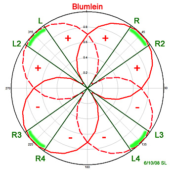
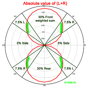
Blumlein microphone setupIt is interesting in the context of mono reverberation to look at the Blumlein microphone array consisting of two crossed bi-directional microphones without spacing between them. The SRA is +/-360 for this configuration. The angle repeats periodically because of the symmetry of microphones. The mono reverberation is only 4 x 7.5% = 30%. The array exhibits some strange mapping properties, though.
Imagine that a sound source moves clockwise around the microphones on a circle with 10 feet (3 m) radius. Starting at L the signal appears to come from the Left loudspeaker. It is centered between the speakers at 00 and then continues to move to the Right speaker up to R. Between R and R2 the signal comes from the Right loudspeaker only. Then it emerges from the Right loudspeaker and moves to the left, getting weaker as it approaches the center line, only to regain strength as it proceeds to the Left speaker and L3. There it will stay between L3 and L4. Then it emerges from the Left speaker and moves back to the Right speaker to R4. Note that a signal from the right side behind the microphones is being reproduced from the left side of the loudspeakers. The left rear between R4 and R3 is mapped into the Right loudspeaker. Between R3 and L2 the signal moves from Right to Left speaker where it stays between L2 and L. The array has equal sensitivity front and back but low pickup from the sides. I doubt that the Blumlein array is optimal for mapping an auditory scene for stereo loudspeaker playback.
References[1] Joerg Wuttke, Mikrophonaufsaetze [2] Michael Williams, Microphone arrays for Stereo and
Multichannel sound recording, 2004, Vol.1 [5] Helmut Wittek, IMAGE Assistant 2.0 [6] Listen to audio demonstrations of different recording techniques for different audio scenes in the Schoeps Microphone Showroom
--------------------------------------------------------------------------------------------
|
|
| ||||