
|
|
|
|
| LR2 | LR4 | LR6 | LR8 | LR10 | |
| Q0 of stage 1 | 0.5 | 0.71 | 0.5 | 0.54 | 0.5 |
| Q0 of stage 2 | 0.71 | 1.0 | 1.34 | 0.62 | |
| Q0 of stage 3 | 1.0 | 0.54 | 1.62 | ||
| Q0 of stage 4 | 1.34 | 0.62 | |||
| Q0 of stage 5 | 1.62 | ||||
| dB/octave slope | 12 | 24 | 36 | 48 | 60 |
Crossover filters of higher order than LR4 are probably
not useful, because of an increasing peak in group delay around f0.
Top
The 24 dB/oct LR4 crossover filter provides outputs which are 360 degrees offset in phase at all frequencies. At the transition frequency Fp the response is 6 dB down. The electrical network will only give the targeted exact acoustic filter response, if the drivers are flat and have wide overlap. This is seldom the case. The steep filter slopes make the combined acoustic response less sensitive to magnitude errors in the driver responses, but phase shift errors usually have to be corrected with an additional allpass network. (xo12-24b.gif, 38xo_eq1.gif, models.htm#E) Top
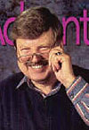
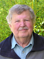
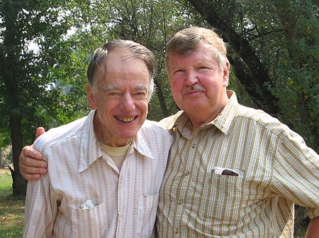 Russ Riley and Siegfried Linkwitz, September 2006, Douglas City, CA |
| In the
sixties,
early seventies, I
worked with Russ Riley at Hewlett-Packard's Palo Alto R&D laboratory
for the development of RF and Microwave test equipment. Like many other
engineers we had "G-Jobs", building such things as
electronic ignitions for our VW bugs and vans, FM receivers, phase-locked
pulse width FM demodulators, short-wave receivers, audio pre- and power
amplifiers, third octave audio analyzers, headphone equalizers, and of
course, loudspeakers. After measuring the acoustic and electrical
responses of commercial speakers we equalized them and tried to understand
why they were designed with strange looking driver layouts, used large
baffles, were stuffed with a variety of internal damping materials and
used various box stiffening and damping techniques. Eventually we
completely redesigned them and built our own speakers. Russ and his wife,
Vicky, an accomplished organist, always had the most critical and reliable ears. He
was an ingenious design engineer, a strong contributor, who inspired and
challenged many of us on our HP and unofficial design projects. Russ retired after over 40 years in R&D for HP/Agilent and now lives with his wife in a remote mountain valley, in a genuine log cabin, amongst pear, plum and walnut trees, berry bushes, chicken and deer, the sounds of a large creek, and the pine and fir trees that climb up the slopes. He died peacefully in his log cabin on December 6, 2010. |
A first order allpass filter section with flat amplitude response but phase shift that changes from 0 degrees to -180 degrees, or -180 degrees to -360 degrees, is often used to correct phase response differences between drivers. Multiple sections may delay the tweeter output and compensate for the driver being mounted forward of the midrange. Active crossover circuits that do not include phase correction circuitry are only marginally useable. (allpass.gif, allpass2.gif, models.htm#E, 38xo_eq1.gif) Top
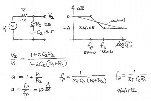
This type of circuit is useful to bring up the low frequency response in order to compensate for the high frequency boost from front panel edge diffraction. It can also serve to equalize the low frequency roll-off from an open baffle speaker. (shlv-lpf.gif, 38xo_eq1.gif) Top
A passive RC version of the shelving lowpass is shown below.
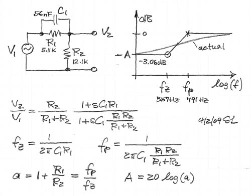
A circuit used to boost high frequencies or to smooth the transition between a floor mounted woofer and a free standing midrange. (shlv-hpf.gif, 38xo_eq1.gif, models.htm#F) Top
A passive RC version of the shelving highpass is shown below.
Notch filters are used to introduce dips in the frequency response in order to cancel driver or room resonances. The three circuits above have the same response. A) is difficult to realize because of the large inductor. B) is used to remove the peak in the 6 dB/oct dipole response. C) gives convenient component values for room EQ below 100 Hz. (room EQ, inductr1.gif, inductr2.gif, 38xo_eq1.gif ) Top
Equalization of the dipole frequency response roll-off usually requires not only a 6 dB/oct boost towards low frequencies, but also removal of a peak in the response. (Models A2) The three circuits differ in their ability to remove such peak.
A) The shelving lowpass filter cannot correct for a peak.
B) The bridged-T based circuit is limited in the shape
of curves that can be realized. It has also higher gain for opamp noise
than signal at high frequencies.
C) The shelving lowpass with added notch filter is the most flexible circuit. (models.htm#D)
Top
A majority of drivers exhibit second order highpass
behavior because they consist of mechanical mass-compliance-damping systems.
They are described by a pair of zeroes at the s-plane origin and a pair of
complex poles with a location defined by Fs and Qt. The circuit above allows to
place a pair of complex zeroes (Fz, Qz) on top of the pole pair to exactly compensate
their effect. A new pair of poles (Fp, Qp) can then be placed at a lower or a higher
frequency to obtain a different, more desirable frequency response.
This allows to extend the response of a closed box woofer to lower frequencies,
in the above circuit example from 55 Hz to 19 Hz, provided the driver has adequate
volume displacement capability and power handling.
The equalizer frequency response is shown below, correcting for a woofer with
peaked response (Qp = 1.21) and early roll-off (Fp = 55 Hz), to obtain a
response that is 6 dB down at 19 Hz and with Q = 0.5 .
The associated phase and group delay responses are shown below.
Not only is the frequency response extended, but the time response is also improved, as indicated by the reduced overshoot and ringing of the lower cut-off highpass filter step response.
It can be seen from the s-plane description of the transfer functions that the complex poles of the driver in the box are canceled by a set of complex zeros in the equalizer. The specified real axis poles of the equalizer, together with the driver zeros at the s-plane origin, determine the overall loudspeaker response in frequency and time.
The equalizer action is difficult to visualize in the time domain, because the driver output waveform is the convolution of the input signal s(t) with the impulse response of the equalizer h1(t), which in turn must be convolved with the impulse response h2(t) of the driver. Convolution is a process whereby the current value of the time response is determined by the time weighted integral over past behavior. Below are the responses of driver, equalizer and driver-equalizer combination, if the input signal s(t) is an impulse.
More illustrative are the responses to a 4-cycle, rectangular envelope 70 Hz toneburst s(t). For example, the driver output is the convolution of the burst s(t) with the driver's impulse response h2(t). Note that the driver phase leads the input signal, as would be expected for a highpass response. Upon turn-off of the input burst at 57.14 ms the driver response rings towards zero, governed by Fp = 55 Hz and Qp = 1.21.
The equalizer output response lags its burst input. This
signal will force upon the driver a response correction so that it is no longer
dominated by Fp
= 55 Hz and Qp = 1.21. The equalizer output signal is convolved with the
impulse response h2(t) of the driver to obtain the desired equalized
driver output. Now, the decay of the driver output follows the 2nd order highpass filter response determined by Qp = 0.5 and Fp = 19
Hz of the equalizer, after the excitation has stopped.
Of course, none of the driver mechanical
parameters like mass, compliance and damping have been changed in the process of
equalization, only the input signal to the driver has been modified.
The above circuit can also be used to correct the low frequency roll-off of a tweeter so that the equalized tweeter becomes a filter section in an exact LR4 acoustic highpass. (f0Q0fpQp.gif, pz-eql.xls, f0Q0.gif, FAQ15, sb80-3wy.htm, sb186-48.gif , sb186-50.gif)
The 'CFL
Linkwitz Transform Designer with Monte Carlo Sensitivity Ananlysis' by
Charlie Laub makes component value selection easy and shows the effect of
component tolerances upon the frequency response. Keep in mind that the LT is
based on a measurement of driver parameters Fs and Qt. Only the small signal
parameters are easy to define. Fs and Qt change with increasing signal level and
to varying degree for different drivers. This makes the equalization imprecise,
but it remains effective in practice.
Top
A major advantage of line-level active crossovers is the efficiency with which drivers of different sensitivity can be combined in a speaker system. The three circuits use linear taper potentiometers but obtain a gain variation that is approximately linear in dB. Circuits B and C assume a 10k ohm load such as the input impedance of the power amplifier. Circuit A is optimal between filter stages because of its low output impedance. The placement of the variable gain stage in the filter chain must be carefully considered, because it affects noise performance and signal handling. (gain-adj.gif, attnrout.gif, 38xo_eq1.gif) Top
Occasionally a fixed attenuation of A dB or a is needed for the input voltage V2 of a circuit stage with input impedance R3 when driven from an operational amplifier with output voltage V1. In the example below a 3 dB (a=1.41) attenuation is desired. The load Rin that is seen by the opamp should be about 2000 ohm. The following amplifier stage has an input impedance of 10k ohm.
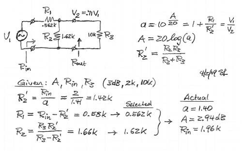
For designing an attenuator with specified output impedance Rout see: attnrout.gif
The output stage of the filter must be capable of driving cables, which typically have a capacitances in the order of 150 pF per meter length, without going into oscillation. A 196 ohm resistor maintains a resistive load component and tying output to negative input for out-of-band frequencies (>100 kHz) reduces loop gain. All of the above circuits can drive cables if operational amplifiers such as the OPA2134 or OPA2604 are used. In most cases it is not necessary to have a separate line driver.
Performance of active circuits should always be checked for inter-stage clipping, and for oscillation with a wideband (>10 MHz) oscilloscope. Top
I recommend to leave the effort of building a regulated power supply to one of the many vendors that offer wallplug and tabletop models. An output specification of +/-12 V to +/-15 V DC at >250 mA and with <1% ripple and noise will suffice. Often such supplies can be found at electronic surplus stores. Top
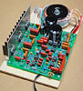
To simplify the construction of active line-level equalizers and crossovers I offer three printed circuit boards, ORION/ASP, WM1 and MT1. The circuit traces are laid out to allow for a variety of filter designs. It is up to the user to determine the actual circuit configuration and component values. Then the necessary components and jumpers are loaded at the appropriate locations on the board to obtain the desired filter response. I will provide specific information for assembling the PHOENIX crossover/equalizer on the ORION/ASP pcb and a Linkwitz Transform on the WM1 pcb.
WM1 is designed to implement the functionality of circuits 1, 5, 6, 7, 8, 9 or 10 and various combinations of these. The circuit board provides two of the topologies below for two channels of equalization or for a more elaborate single channel response correction.
The WM1 board can be used for:
MT1 is designed to implement the functionality of circuits 1, 2, 3, 4, 5, 10 or 11 and various combinations of these. On the circuit board are two of the topologies below.
The MT1 board can be used to construct:
The circuit boards are practical tools to experiment with and to learn about active electronics. You will find that active loudspeaker systems give you the freedom to match drivers of greatly different sensitivities, are easier to design, and can give greater accuracy of sound reproduction, than is possible with passive, high-level crossovers and filters.
See the Circuit Board page for ordering information. Top
.
Much useful information can be obtained from application notes of the various opamp manufacturers. If you need a refresher or an introduction to circuits, then read:
[1] Martin Hartley Jones, A practical introduction to electronic circuits, Cambridge University Press, 1995. It is a well illustrated, easy to read, yet technically solid text. It covers a broad range of devices - from tubes to ICs - and many basic circuit functions.
The following books cover a range of concepts and go into depth on specific, relevant topics to strengthen understanding of electronic circuits and electro-acoustic models.
[2] Herman J. Blinchikoff & Anatol I. Zverev,
Filtering in the Time and Frequency Domains, John Wiley, 1976. A broad and
fundamental look at filters.
[3] Arthur B. Williams & Fred J. Taylor, Electronic Filter Design
Handbook, McGraw-Hill, 1995. Design and analysis formulas for all types of
filters.
[4] Jasper J. Goedbloed, Electromagnetic Compatibility, Prentice
Hall,1990. Fundamental concepts and practices for dealing with radio frequency
interference.
[5] Henry W. Ott, Noise Reduction Techniques in Electronic Systems, John
Wiley, 1976. Practical steps to combat RFI.
[6] Manfred Zollner & Eberhard Zwicker, Elektroakustik, Springer,
1998. The most comprehensive and solid engineering
level presentation of electro-acoustic transducers and related subjects.
In
German, no comparable English language text available, to my knowledge.
[7] Walter G. Jung, editor, Op Amp Applications, Analog
Devices, 2002. Everything you ever wanted to know about using operational
amplifiers, and not just at audio frequencies.
Top
------------------------------------------------------------------
| Build-Your-Own
| Main Panel | Dipole Woofer | Crossover/EQ
| Supplies |
| System Test | Design Models | Prototypes
| Active Filters | Surround
| FAQ |
|
| ||||