
| Build-Your-Own
| Main Panel | Dipole Woofer | Crossover/EQ
| Supplies |
| System Test | Design Models | Prototypes
| Active Filters | Surround
| FAQ
|
For a better understanding of what I had in mind when I
designed the PHOENIX loudspeaker system, you should read the <Concepts ...> pages,
which give you general observations that influenced
this unconventional speaker project. The reasons behind specific design
solutions are addressed on the | Design Models | page and in Ref.2.
Measured frequency response curves for the PHOENIX are shown on the | System
Test
| page.
The project documents the evolution from a previous active speaker
system in which I used two small satellites and a closed box woofer with a novel
equalizer to extend its low
frequency response .
You will find helpful information about many issues in speaker design in the description of that
earlier project, Ref.12.
Take a look at page 1 or the full
article.
In general, I tried to give specific meaning to every sentence on this
web site. If you do not find your answer or are confused after reading what I
said, then do not
hesitate to send me your question. And, for my benefit, let me know what you did with my
response. I always appreciate your recommendation for a well recorded piece of
music to listen to.
Should you have built the PHOENIX or parts thereof and
made interesting observations or found
ways to improve the design, then send me a note. I am always interested in new
insight on how to move sound reproduction closer to the original. But please,
don't ask me what changes are necessary to accommodate your favorite driver. I
think I have outlined in detail how you can determine that for yourself. If not,
then stick exactly to the PHOENIX project.
-----------------------------------------------------------
Q1 - Why do you use 8" drivers for the midrange when
6.5" or 5" drivers would give better off-axis response?
Q2 - My room size is less than 250 ft2
(22m2) and I need a smaller speaker. How can I modify the PHOENIX
design?
Q3 -
How do I upgrade the system for rooms larger than 600 ft2 (55m2),
or because I like to play it larger than live?
Q4 - I want to use woofer XYZ which has larger Xmax
than the 1252DVC. Which other parameters are important?
Q5 - How much sound output can you get
from the open baffle woofer?
Q6 - How much power will it take to
drive the woofers?
Q7 - The price of the Scan-Speak
drivers is a problem. Is there any valid substitute without changing the design?
Q8 - Diffraction. Would a narrower (<12.5")
main panel give sharper stereo imaging, due to reduced delay of edge diffraction?
Q9 - Could the length of the main panel be
extended so that separate stands are not required?
Q10 - Could the woofer be adapted to work
with existing panel speakers - e.g. Quad ESL63?
Q11 - What is the total cost of all the
hardware for building a pair of PHOENIX loudspeakers?
Q12 - What happens to the parameters Vas,
Qms, Qes and Qts when you connect the two voice coils of the 1252DVC in series?
Q13 - Is
a printed circuit board
for the crossover/eq available?
Q14 - What is the low frequency sound
pressure level from an open baffle speaker with a given effective piston area and
excursion?
Q15 - How would you modify the
crossover/eq
circuit to work with a "regular" small monitor, instead of the main
panel, and use the dipole woofer?
Q16 - Could you drive the main panel with
a tube amplifier?
Q17 - Why do you not show waterfall
response plots for the PHOENIX when your test equipment is capable of producing
them?
Q18 - Which types of distortion do you
measure?
Q19 - Why do you use a 12
dB/oct crossover
between woofer and midrange when the crossover to the tweeter is at 24 dB/oct ?
Q20 - What is the sound
pressure level at 1 m for 1 W of power under anechoic conditions?
Q21 - Why does SPL
increase 6 dB for two drivers in parallel when the electrical power consumed
only increases by 3 dB?
Q22 - How would you
describe the sound of the PHOENIX?
Q23 - Can you point me
towards people who have built the PHOENIX?
Q24 - What is your process
for designing an open baffle speaker?
Q25 - Why do you not use a
rear firing tweeter or a dipole ribbon tweeter?
Q26 - Why use active
crossovers when passive crossovers require fewer components and amplifiers?
Q27 - How
do I test the PHOENIX crossover/equalizer circuit board?
Q28 - How
high in frequency can you push the dipole woofer?
Q29 - How
do you measure cone excursion of a driver?
Q30 - Can
a dipole woofer be placed in a room corner?
Q31 - Is
there an optimum room placement for a dipole?
Q32 - How
would you increase the output capability of the Phoenix?
Q33 - Is a
pre-assembled crossover/equalizer available?
Q34 - What
is the optimum Qts for the drivers of a dipole woofer?
Q35 - How
does the new ORION compare to the PHOENIX?
Q36 - Are
there better drivers for the PHOENIX?
Q37 - What
cables and interconnects do you recommend?
Q38 - How
do diffraction effects show up?
Q39 - How
much power does it take to drive a dipole woofer?
Q40 - Can
the PHOENIX be build with passive crossovers?
------------------------------------------------------------------
Q1 - Why do you use 8" drivers for the midrange when
6.5" or 5" drivers would give better off-axis response?
A1 - I am using 8" drivers because the crossover to
the woofer will be around 100 Hz and because an open baffle speaker has to move more air than
a box speaker due to the progressive acoustic short circuit between front and
back. The open baffle gives significantly wider dispersion at high frequencies than a
box speaker with the same 8" driver on the same baffle, see Ref.
2, Design Models F. This is caused by the radiation
from the rear of the baffle, having undergone enough phase shift as it comes
around to the front, so that it adds to the total sound at off-axis angles. See Dipole
Models.
For almost all drivers, as you go down in driver size, the
excursion
capability drops. Thus, the linear volume displacement - which makes SPL - goes
down even faster than diameter squared. What is gained in wider dispersion,
which is inversely proportional to diameter, is more than lost in increased
distortion. Low distortion is higher on my priority
list than dispersion. Since dispersion is widened with a properly sized
open baffle, there is no good reason for using a smaller diameter driver other
than if the 8" driver had poor behavior in its cone breakup frequency
region.
A 8" driver will typically have twice the useable volume
displacement of a 6.5" driver, but the effective diameter increase is only
30%. Thus, when used in an infinite baffle or in a box, the 8" driver will have the same dispersion at 1.5 kHz as the
6.5" driver has at 1.95 kHz. The smaller drivers are so popular in
commercial products because narrow loudspeaker cabinets are much more acceptable
in the home for visual reasons, a trend that is conveniently supported by
theories about the detrimental effects of edge diffraction. Note also how many of these
speakers use two
drivers in MTM or MMT layouts to obtain adequate output.
Check out my distortion test
results for midrange drivers. Top
Q2 - My room size is less than 250 ft2
(22m2) and I need a smaller speaker. How can I modify the PHOENIX
design?
A2 - You could eliminate one of the 8" drivers and
make the main panel only 16" tall. This will sacrifice 6 dB in acoustic
output capability for the same non-linear distortion level. The gain of the
midrange channel in the crossover/eq needs to be increased 6 dB. I would not
recommend to also go to a single woofer, i.e. 6 dB less bass output, because
subjectively this is a much more significant reduction in output capability (observe
the close spacing of the equal loudness contours at low frequencies,
Fletcher-Munson). The reduced height main panel would also make for a high
performance center or surround speaker with very uniform and smooth off-axis
response, but for distortion should not be pushed below 100 Hz.
A second alternative is to eliminate the woofers all together
and to extend the main panel response from the present 100 Hz down to 50 Hz. To
maintain the same SPL down to 50 Hz, the 8" drivers must move with 4x the
excursion of 100 Hz. Thus, for the same distortion, output is reduced by 12 dB,
but probably more like 20 dB, because distortion increases much more rapidly
with increasing excursion. For the crossover/eq circuit you would need to change
the midrange high-pass filter 90HP to 50 Hz and the 90-500LP to a 50 Hz to
500 Hz low-pass of appropriate gain. Top
Q3 -
How do I upgrade the system for rooms larger than 600 ft2 (55m2),
or because I like to play it larger than live?
A3 - Now you are into a 4-way system. You could add two 10" drivers (e.g.
Scan-Speak 25W8565) in the space below the main panel as was done in the Audio
Artistry Beethoven and double up on the woofers. If that is not enough
capability, then you might add two more 10" drivers on top of the main
panel and use eight 12" drivers for each woofer as in the Audio Artistry
Beethoven-Grand loudspeaker system. Extreme as these designs may seem, the goal
here is to keep non-linear distortion low at high volume levels or, conversely,
have very low distortion at normal levels.
I think it is important to be able to play back at live like
levels. If the system has low distortion it will not sound loud, just natural.
The level needs to be realistically high, so that the ear produces the same
distortion and timbre as it would at a live event. Then you can experience
maximum involvement and enjoyment.
The crossover/eq for a 4-way system is considerably more
complex than the 3-way circuit for the PHOENIX. But, if you like a serious challenge, then
you might follow my 4-way
functional block diagram and use circuit topologies from the PHOENIX
for the individual blocks. You can use two printed circuit
boards to realize all functions. Be sure to perform free-field and ground plane
acoustic measurements of the mounted drivers before, during and after designing
the circuits to ensure proper polarity and addition of all driver outputs and flat frequency
response. Design Models F1
CAUTION: Such 4-way open-baffle speaker project will lead to
endless questions and frustration unless you have good electrical and acoustic
measurement capability and a solid understanding of what each element in the
system is supposed to do. You cannot adjust relative channel levels by ear and
expect to obtain a speaker that is true to the original. Unless you have these
resources your chances of improving on the PHOENIX are slim and you might even
end up with lower performance than if you had followed the PHOENIX design.
I consider the 3-way PHOENIX speaker system described here
as more practical and useful for a wider range of audio enthusiasts,
particularly since its output capability can be increased
comparatively easily.
Top
Q4 - I want to use woofer XYZ which has larger Xmax
than the 1252DVC. Which other parameters are important?
A4 - I use two drivers to
double volume displacement and to reduce even order harmonic distortion by
running them with opposite cone motion. The requirements for an open baffle
driver are quite different from those for a closed or vented
box design.
- Fs < 20 Hz
- Qts = 0.5 - 0.8
Smaller values of Qts increase roll-off towards the
low frequency end and require
more equalization than the 6 dB/octave boost for dipole cancellation that I used
in the
10-300LP stage of the Crossover/EQ. Most drivers have too strong a motor for
dipole applications and are over-damped in an open baffle cabinet. When the
driver is mounted into the woofer cabinet, air mass is added to the free-space
moving mass of the driver. This lowers the mechanical resonance frequency Fs and
increases Qts by approximately the same percentage. The amount of change is
difficult to predict accurately and best measured using f0Q0.gif
from Ref.12.
I do not recommend the use of drivers with very small magnets and Qts >>
0.8 in an attempt to compensate for the 6 dB/oct open-baffle roll-off with a
rising driver response. Such equalization is crude at best. I prefer active 6
dB/oct low-pass filter equalization. The filter cut-off frequency should be set
in conjunction with Qts and Fs to avoid a peak in the group delay of the
resulting 3rd order acoustic high-pass filter. See FAQ19 for
acoustic effects.
- Sensitivity: <10 W for Xmax at Fs
- Power handling >50 W
- Frequency range 15 -100 Hz
- Xmax > 6 mm
Note that Xmax = 0.5 [(voice coil height) - (air gap
height)] is merely proportional to the linear excursion.
Different drivers with the same Xmax do not necessarily have the same linear
excursion range! The design
and construction of the spider, surround, and magnet gap region have strong
influence on the actually useable excursion range before distortion becomes
excessive.
A driver with Xmax = 12 mm will generate quite a bit of aerodynamic noise, i.e.
distortion, at such high excursions. The space behind the spider needs to be
open to the outside to minimize noise. The pole piece should have a large vent,
or the cone should have no dust cap, so that air trapped behind the dust cap
does not contribute noise.
For a qualitative evaluation of a new woofer perform a simple test. Put a dot of
white paint on the cone or dust cap to monitor excursion. Connect the driver to a power amplifier and
drive it from a signal generator set to 35 Hz. Hold the unbaffled driver in your hands. Increase the generator output and observe how quiet the
driver remains and how much excursion it can handle before sounding obnoxious.
Remember that an open baffle cabinet will not attenuate this noise. Lower the frequency
and repeat the test. Be careful not to overheat the voice coil or to destroy
the driver mechanically!! The burst capability of the Agilent 33120A Arbitrary
Waveform Generator is wonderful
for this work. Unfortunately, the majority of drivers that I have evaluated
required no further investigation after this test.
The Gefco X6100 and
especially an Eminence Speaker Corporation 12-6676 proto type performed well
and are very applicable. The Gefco X6100 driver is available from Madisound
.
The Eminence 12" proto type was built on a similar
platform as the Adire
Audio "Shiva" driver,
but specifically optimized for open baffle application. It would require a
slightly wider cabinet, but should give 3 to 5 dB more SPL for the same
distortion level as the Gefco X6100. Cost, though, is at least twice that of the X6100. If you listen to a lot of organ music and
woofer cabinet size is very important to you, then instead of stacking two PHOENIX woofers
with four X6100, you could have nearly the same SPL output from a pair of theses
drivers in a smaller cabinet. For an update and somewhat disappointing conclusion of this project see
Woofer2 and for a real, higher output alternative see Woofer3.
There are possibly other 12" or 10" drivers on the
market with equal or larger useable, linear volume displacement than the 1252DVC
and X6100 . These two drivers, though,
have proven themselves for open baffle application and provide a sensible tradeoff between
cabinet size, distortion performance and cost.
I measured the following parameters for these two drivers:
1252DVC: Re = 5.5+5.5 ohm, Fs = 17.4 Hz, Qts = 0.5, Xmax = 0.5"p-p.
X6100: Re = 11.4 ohm, Fs = 12.7 Hz, Qts = 0.43, Xmax = 0.5"p-p,
voltage sensitivity when mounted in woofer baffle is about 1 dB lower than for
the 1252DVC. Top
Q5 - How much sound output can you get
from the open baffle woofer?
A5 - I give a formula in Ref.
2 and in Design Models A1 that relates the sound pressure level from a driver on an open baffle to
the SPL from the same driver in an acoustically small closed box, assuming that
both have the same cone excursion.
Fequal = 0.17 v / D
At frequency Fequal the SPL is the same for either driver arrangement. The open
baffle driver output decreases at 6 dB/oct below this frequency relative to
the closed box. Above this frequency it increases to an on-axis peak that is 6
dB higher than the SPL from the box. The peak occurs when the distance D between
front and rear equals 1/2 wavelength, i.e. when the rear wave is phase shifted
180 degrees and in phase with the front wave.
For the PHOENIX woofer D = 19" (0.48 m). With v = 343 m/s
Fequal = 120 Hz
Thus, for on-axis SPL at 120 Hz, one 12" driver in the open baffle cabinet
is equivalent to the same 12" driver in a closed box. At 30 Hz, though, the
open baffle SPL has dropped to 1/4, i.e. it would take four 12" drivers to
maintain the same SPL as the single 12" driver in a box, when all of
them are driven to the same excursion. (See also FAQ14)
At 30 Hz the two woofer cabinets of the PHOENIX are equivalent to a single
12" in a closed box, assuming that the box speaker is flat to 13 Hz (-3 dB). Above this frequency, of course,
the two open baffles generate
considerably more SPL than the single 12" driver in a box. At 60 Hz
the dipoles would be equivalent to two of those 12" box woofers and at 120
Hz equivalent to four in terms of maximum SPL. You can add 6 dB to this
capability by doubling the dipole woofers and stacking them on top of each other
for a height of 28", but this might negatively affect the WAF. The primary
benefit of the stacked woofer arrangement would be reduced non-linear distortion
when listening at the same SPL as before.
A lot of air is shuffled back and forth between the two sides of the open
cabinet. This sets up a strong sound velocity field but our ears only respond to
sound pressure and we do not hear it. This is wasteful of cone excursion but the price to
pay for natural bass reproduction. You can see why the open baffle woofer will
never be a popular commercial item, when a majority of consumers loves excessive
bass, and when a dipole woofer will just not get the room going in all its
resonant modes for additional boom. Top
Q6 - How much power will it take to
drive the woofers?
A6 - Not much. At Fs it takes maybe around 5
W to drive a 12" unit to full excursion in free air. It takes just a little
bit more in the open baffle cabinet because of the air mass loading. More power
is needed as frequency goes up. I have found - by monitoring the p-p voltage
across the woofer terminals - that each woofer channel is easily served by a 50
W amplifier. Top
Q7 - The price of the Scan-Speak
drivers is a problem. Is there any valid substitute without changing the design?
A7 - The Vifa D27TG-45-06 (also the reliable
D26TG-35-06) fabric dome or D25AG-35-06 aluminum dome tweeter and
P21WO-20-08 woofer could be alternate drivers for the main panel. The mounting
hole dimensions need to be changed and some of the component values in the
crossover/eq. While this will give you an excellent, natural sounding speaker,
it has not quite the same clarity and dynamics as the PHOENIX. See FAQ22.
Many other drivers could be used with the same crossover/xo
circuit topology. If you leave the crossover frequencies and the main panel
dimensions unchanged, then only the woofer and tweeter gain levels, the 1440PH
phase shifting networks, and the 400NF notch filter might have to be readjusted.
If you change the main panel dimensions, then you are in your own ball game, but
the circuit topology should still give you all the necessary functionality.
Top
Q8 -
Diffraction. Would a narrower (<12.5")
main panel give sharper stereo imaging, due to reduced delay of edge diffraction?
A8 - Diffraction is a difficult subject. I
will try to give a simplified explanation of how diffraction works for an open
baffle speaker after looking first at diffraction in general, and then for
a closed box speaker. See FAQ 38 for actual measurements of
diffraction.
Fundamentally, diffraction
is about the transition between an acoustic wave propagating from one space
first into another space of different volume. The effect, at an observation point
at large distance from the source of the wave, is a change in sound pressure and, correspondingly, a
change in the frequency response. The effect will be different whether the point
is on-axis or off-axis. Take, for example, a small source on a flat baffle. At
low frequencies, where the wavelength is much larger than the distance from the
source to the baffle edge, the source radiates essentially unimpeded into full
space (4pi). At higher frequencies and shorter wavelengths, the baffle begins to
look more like a large plane because it takes increasing numbers of wavelengths
to reach the edge of the baffle. The source now radiates essentially into
half-space (2pi), but with delayed reflections from the baffle edge that cause
ripples in the frequency response, and which become weaker as the edge recedes
in terms of wavelengths. On average, the pressure at a distant on-axis point in space
will be 6 dB higher at high frequencies, than at low frequencies.
If the baffle is not flat, but tapered 30 degrees such that
the source is located at the tip of a 120
degree circular cone of finite extension, then at short wavelengths radiation
will be
into 3pi-space. At long wavelengths radiation is again into 4pi-space and
on-axis pressure increases only 20log(4/3) = 2.5 dB on average and with ripples
in the frequency response from the edge of the cone.
Let's now look in more
detail at diffraction at the front panel edges of a closed box speaker with
rectangular baffle. Assume
the driver cone moves abruptly outward and causes a local air pressure
increase. The pressure increase propagates at the speed of sound (343 m/s) away
from the cone into an environment that is bounded on one side by the front
panel. Until the pressure wave front reaches the edge of the panel, it looks as
if the driver was radiating into half-space. When the wave encounters the edge
it suddenly sees an expanded space and the pressure drops. This pressure drop
occurs all around the front panel edge, though at slightly different time,
depending upon the distance from a particular point on the edge to the cone. All
together, the pressure is reduced to 1/2, i.e. it drops 6 dB, because the volume
of space encountered by the wave has doubled. We can think of this phenomenon as
if a delayed wave of half the strength of the original wave and with opposite
polarity was propagating out from the circumference of the front panel.
When we monitor this behavior from a point in front of the
box (e.g. 1 m), then we observe first the arrival of the original pressure
increase and a little time later a pressure decrease when the wave from the
cabinet edge arrives. Note, that our conceptual model assumed that the pressure
increase occurred in such a short time interval, that we can resolve the ensuing
pressure decrease, which is no longer abrupt, but smeared because of the unequal
distance from the panel edge points to the cone. If the panel had an effective
width of 8" (0.2 m), and the cone was centered on the baffle, then the pressure decrease would occur 0.1m / 343m/s =
292 microseconds after the increase. To resolve the two events as separate from
each other, the pressure must reach its final value in an interval shorter than
292 us, which means the driver must have a bandwidth greater than 1 / 292us =
3430 Hz. A slower pressure increase as produced, for example, by a 300 Hz tone
would almost immediately be decreased by edge diffraction to 1/2 its starting
value.
Thus, if we look in the frequency domain, the pressure
response from an idealized point source on a finite size baffle will start at
low frequencies with a value that is 6 dB lower than the value around which the
response oscillates at high frequencies. The oscillation occurs due to the
phasing between initial sound and edge diffraction, adding and subtracting from
each other. By making the baffle narrower the transition to the oscillatory
region moves higher in frequency, e.g. to above 2000 Hz in the above example. As
the driver itself, due to its piston diameter, becomes more directional
with increasing frequency, it also illuminates the panel edge with less
strength, which then reduces response irregularities caused by diffraction. This
comes into play when the effective piston diameter becomes larger than 1/3 of a
wavelength. A smaller diameter driver, 6" versus 8", illuminates the
the panel edge stronger than the larger driver for a given frequency and panel
width, because it is less directional of itself. This effect is offset to some
extend by making the cabinet proportionally narrower, which moves the response
irregularities up in frequency. I think the popularity of 6" drivers is
mainly driven by greater consumer market acceptance of visually less obtrusive
narrower cabinets.
In general, the effect of cabinet diffraction can be observed
and measured in the frequency domain as on-axis and off-axis frequency response
irregularity. It shows especially strong in the on-axis response of symmetrical
driver layouts. Diffraction effects can be seen most easily in the time and
amplitude response to shaped tone bursts.
References: H. F. Olson, Acoustical Engineering, 1957, pages
21-23. Anyone attempting to come up with a simple calculation of diffraction
should first read: G. G. Muller, R. Black, T. E. Davis (all from Bell Labs), The
Diffraction Produced by Cylindrical and Cubical Obstacles and by Circular and
Square Plates, JASA, Vol.10, 1938.
If I have not lost you by now, then
let's talk about open baffle diffraction effects with the above in mind. Assume a
small unenclosed piston source in the center of a circular, flat baffle. The source radiates
towards the front and with opposite polarity towards the back. A pressure
increase in front is associated with a pressure decrease in back of the baffle.
Observing again the response to a stepwise increase in pressure at some on-axis
distance in front of the baffle, we see the initial pressure increase, which
drops to 1/2 when the edge diffracted front side wave arrives. At the same time
we also receive from the backside of the baffle that 1/2 portion of the wave,
which was diffracted around the baffle edge into the frontal hemisphere.
The 1/2 of the backside wave is of opposite polarity to the front wave and
together with the front edge diffraction cancels the front wave completely(!).
If the baffle had a 12" (0.3 m) diameter, then we would observe a
0.15m / 343m/s = 437 us duration pulse in response to the pressure step
from the point source.
You might say this is a much stronger diffraction effect than
for the closed box - and you are correct - but it is also the characteristic
response of an open baffle, dipole source - after equalization. Modeling the
response with a stepwise pressure increase and decrease implies an integration
of the systems impulse response. Integration in the time domain is equivalent to
boosting
the low frequencies at 6 dB/oct in the frequency domain. The 437 us duration
pulse is described by a sin(f)/f frequency response function, which exhibits
a flat response up to the frequency where the diffracted wave is delayed by 1/2 wavelength, i.e.
where it adds in phase to the initial wave. For the 12" baffle this
frequency is at 343m/s / 0.3m = 1143 Hz. At higher frequencies the response
rolls off at 6 dB/oct with periodic dips and peaks unless the equalizing 6
dB/oct boost is leveled out. See Design Models A.
In practice you would not use a circular baffle to avoid the
strong, comb filter like oscillations in response at high frequencies. A rectangular
baffle smoothes out diffraction irregularities. In addition, as the driver itself
becomes more directional with increasing frequency, the shape of the baffle
becomes less critical because its edges are less illuminated.
Ultimately, it is the on-axis and off-axis frequency response
of the equalized speaker that tells how well diffraction effects have been
integrated into the design, regardless of the speaker type, cabinet shape,
baffle width or drivers used. Narrower cabinets are just easier to work with for
box speakers. A real feature of the PHOENIX is the smooth off-axis response that
mimics the on-axis response, but with decreased amplitude as the angle is
increased. You can see various frequency response data on the | System
Test
| page and in Ref. 2 .
There is more to sharp stereo imaging than a narrow baffle.
Top
Q9 - Could the length of the main panel be
extended so that separate stands are not required?
A9 - Extending the main panel to the floor
would create a large, potentially radiating surface area, if excited into
vibration. I would recommend to extend the back spine and side panels, instead.
The three legs would need to be cross-braced and solidly tied into a base.
Suspending the panels from the ceiling is probably the
optimum solution if hooks can be safely fastened to carry the panel weight. Rope
and panel mass form a mechanical low-pass filter between driver cone movement and
ceiling. The speaker is operating above the pendulum resonance and in the filter
cutoff frequency range.
The problem with standing speakers on the floor is the
potential transmission of structure borne vibrations into the floor. Spikes
should not be used on suspended wood floors, because the speaker might excite
the large floor area into spurious panel vibrations and subsequent re-radiation
of sound. It is better to place a mechanically lossy medium, such as a thick,
heavy felt mat, between the speaker base and the floor. Top
Q10 - Could the woofer be adapted to work
with existing panel speakers - e.g. Quad ESL63?
A10 - A PHOENIX like open baffle, dipole woofer would be
the ideal complement to a variety of planar, open baffle, dipole speakers ( e.g. photos at
Audio
Page ).
The woofer channel of the crossover/eq circuit could
remain
unchanged for the 100 Hz, 12 dB/oct, L-R low-pass filter section of the crossover
between woofer and existing speaker. The gain setting resistor ladder values
(8.25k & 5.62k) would have
to be modified to account for differences in sensitivity between woofer
and existing speaker.
Assuming that the existing speaker has low frequency
extension to at least 50 Hz, but is limited in SPL capability, then the high-pass
filter section of the crossover, to drive the existing speaker, could be simply
formed by a second order HP with two real axis poles at 100 Hz. The filter
response could be
realized with two cascaded 1st order Butterworth filters or the 12 dB/oct circuit topology
of xo12-24.gif, which is also used on the crossover/eq
printed circuit board.
Thus, you could modify the second 1440HP filter section in
the tweeter channel to realize the 100 Hz high-pass. Simply replace the 2.37k and
4.64k resistors with 51.1k resistors. The two 33 nF capacitors remain. None of
the other components in the tweeter and midrange channel are loaded onto the
circuit board.
Add a jumper wire from the buffer output to the 33 nF input capacitor of the new
high-pass and use the tweeter output to drive the power amplifier of your
existing open baffle speaker. Alternatively, you could use my general
topology printed circuit boards to define your own filter layout and configuration.
The woofer cones and the existing speaker's vibrating panel must be wired to move in
opposite direction at dc - or at extremely low frequencies - for the acoustic
outputs to sum correctly around 100 Hz. (See the main panel and dipole
woofer sections of the System Test page for checking
woofer level and phase.)
If the existing speaker has its own roll-off in the 100 Hz
region, then the crossover high-pass filter design would become more difficult and depend on the
speaker's measured performance. This might be a situation where full
equalization of the midrange highpass behavior becomes necessary. An active
circuit (biquad) allows to shift the poles in the midrange response to the
desired crossover frequency. A circuit with this type of response can be
constructed using one of my general topology printed
circuit boards.
See also FAQ15. Top
Q11 - What is the total cost of all the
hardware for building a pair of PHOENIX loudspeakers?
A11 - The material cost depends, of course,
very much on your supply sources. Here, in the USA, I would estimate the
material cost as follows, but please do not hold me to those numbers:
4x 1252DVC $200
4x 21W/8554
$600
2x D2905/9700
$400 (2x D2904/9800 $400)
Electronic parts & 2 pcb
$400
Power supply $100
XO/EQ chassis $100
Cabinet material
$250
This totals to $2050. Add to this the time and cost of your labor building it,
and the cost of tools and equipment, unless you own those already. In addition
you need 6 power amplifiers which might cost you $2000 or more for a 6-channel,
150 W per channel, amplifier. You can save considerably on amplifier cost by
building your own using the LM3886
power op-amp integrated circuit. 3886amp.gif
You could sacrifice some performance and save about $700 by
using the Vifa P21WO-20 and D26TG-35 drivers instead of the Scan-Speak drivers.
The PHOENIX project, though, is not about building an inexpensive speaker. My
goal was a loudspeaker that gives you true-to-the-original reproduction in
common size, normally furnished rooms. If this is what you want, then go for it.
Top
Q12 - What happens to the parameters Vas,
Qms, Qes and Qts when you connect the two voice coils of the 1252DVC in series?
A12 - The answer is not immediately obvious,
so let's look at a single voice coil first. I will ignore the voice coil
inductance which has little influence at low frequencies.
Using the force-current analogy we can transform the
mechanical driver parameters to appear as electrical components between the
voice coil terminals. The driver moving mass becomes a capacitor C that is
inversely proportional to (B*l)2. The suspension compliance becomes
an inductor L proportional to (B*l)2, and the viscous losses are
represented by a resistor R proportional to (B*l)2. The equivalent
electrical circuit between the voice coil terminals consists of R, L and C in
parallel and then connected in series to the voice coil resistance Re.
Series connection of the two voice coils doubles the wire
length inside the magnetic flux, thus (B*l)2 increases fourfold. Therefore,
C decreases to 1/4th, and L and R increase by a factor of four. Voice coil
resistance Re doubles. As a result, the purely mechanical Qms, which is the
ratio of resistance R to inductive reactance wsL,
stays the same. The purely electrical Qes, which is the ratio of net voice coil
resistance Re to inductive reactance wsL,
becomes 1/2 of the single coil value. Qts, which is the parallel combination of
Qes and Qms, is also approximately halved, provided that Qms>>Qes.
Parallel connection of the two voice coils, however, will not
increase the wire length inside the magnetic flux, thus, R, L, and C are the
same as for the single voice coil. Only the voice coil resistance Re is reduced
to 1/2. Again, Qms stays unchanged, but Qes and Qts are 1/2 of the single voice
coil value. This is completely identical to the series connection of the voice
coils.
In summary, series or parallel connection of the two voice
coils will not change the mechanical parameters, only how they appear
electrically in terms of equivalent R, L and C values. Thus Vas, i.e.
compliance, is unchanged as are mass, mechanical losses, and resonance frequency
Fs. For series or parallel connection of the two voice coils Qms, Qes and Qts are the same.
If only a single voice coil is connected and the other is
left open, then Qes doubles and Qms remains unchanged. Thus Qts increases to
almost twice the value of the dual voice coil case.
In the mass controlled frequency range of the driver its SPL
output versus drive voltage will be the same for series connection of the voice
coils as for a single coil. For parallel connection, however, the SPL doubles
(+6 dB) compared to the single coil connection. Top
Q13 - Is a printed circuit board
for the crossover/eq available?
A13 - Circuit boards are in stock and
available. See | Circuit Board | for further
details and ordering information.
Each board contains the circuitry for one channel, i.e. for
one input and the three outputs for woofer, mid and tweeter. In addition, the board has
circuitry for a -3 dB/dec tilt control, and three notch filters for low frequency room
equalization, in case it is desired. Use of the notch filters, though, presumes
that you have accurate room response measurement capability to determine
resonance center frequency, Q and attenuation required. You will need to
calculate the necessary circuit component values and verify the equalizer
response by yourself. I provide the formulas and a spreadsheet..
The circuit board is silk screened with component designators
and component values. It comes with schematic, material list, loading list,
frequency response curves and notch filter design information. You will need to provide the
electrical components yourself, load them onto the board, solder them and test
the completed board.
The circuit board is also suitable for providing crossover
and equalization when adding the PHOENIX dipole woofer to an existing panel
speaker (FAQ10) or a small monitor (FAQ15).
You probably
want to house multiple boards in a chassis with input,
output and power connectors. The board is 8" wide, by 7" deep, and two
of them fit next to each other in a 17" wide chassis. An
external +/-12 V power supply is recommended.
Alternatively, you might use my general topology printed
circuit boards WM1 and MT1 to define your own
circuit layout and construction. Top
Q14 - What is the low frequency sound
pressure level from an open baffle speaker with a given effective piston area and
excursion?
A14 - The output depends on the path length
difference D for sound reaching the listener from the front and the rear of the
piston. For a flat circular baffle of diameter d, with the piston at its center,
that path length difference is D = d/2, when measured on-axis and at sufficient
distance. For the PHOENIX dipole woofer D = 19" (483 mm) between front and rear
cabinet openings. For the PHOENIX main panel, which is folded back and
rectangular, the effective path difference is more difficult to determine and
approximately
D = 12.5"/2 + 3.5" = 9.75" (248 mm). See Design
Models A.
Using these values for D you can calculate the frequency
Fequal at which the dipole output is the same as that of a monopole, closed box
speaker, with the same volume displacement (see FAQ5). The dipole output
has a slope of 18 dB/oct and the monopole increases at 12 dB/oct for constant
piston excursion with frequency.
Conversely, you can use the MS Excel 4.0 spreadsheet spl_max1.xls
to determine the absolute SPL at 1 m in free space. The excursion limited
frequency response for box and open baffle speaker are shown as graphs and you
can readily compare two different drivers and baffle sizes. For radiation into
half-space add 6 dB to the calculated SPL value. The spreadsheet is based on Ref.
4. Top
Q15 - How would you modify the crossover/eq
circuit to work with a "regular" small monitor, instead of the main
panel, and use the dipole woofer?
A15 - My answer to FAQ10 also applies to this
case. I would imagine that a pair of dipole woofers
added, for example, to a
pair of B&W DM302 would make for a very natural sounding system. The dipole woofer would add bass output capability to the
small monitor with minimal excitation of room modes and boom.
It is very likely that the low frequen cy roll-off of the
small speaker occurs around 100 Hz or somewhere close to the intended 100 Hz
crossover to the dipole woofer. In such case the proposed high-pass filter
solution of FAQ10 will not result in the desired 12 dB/oct crossover, because
the monitor contributes phase shift and roll-off. This problem can be solved by
using the circuit of Fig.9 from Ref.12, which
allows correction of the monitor's frequency response in addition to providing
the required high-pass function. The circuit can be constructed using my general
topology WM1 printed circuit board.
The design for the equalizer proceeds as follows:
a - Seal off any ports on the monitor to convert it into a
closed box speaker with 2nd order, 12 dB/oct roll-off, which is easier to
equalize.
b - Measure the frequency response of the speaker's impedance
between its cable binding posts (including built-in tweeter crossover), as in
Fig. 19, to determine closed box resonance frequency f0 and damping Q0
from the data as shown in Fig.18 of Ref.12. The free-space low frequency
response of a closed box speaker is completely determined by these two
parameters, Fig.17.
Should you measure f0 close to 100 Hz and Q0 close to 0.5,
then it is your lucky day and you need no further crossover high-pass filter to
drive the monitor.
c - Assuming no such luck, insert the found values for f0
an Q0 into the design formulas of Fig.25, with fp = 100
Hz and Qp = 0.5 for the crossover high-pass filter. Note that not all
combinations of Q and f are realizable (k>0) and that you may have to juggle
values a little bit. See Active Filter #9,
f0Q0fpQp.gif, pz-eql.xls
, True Audio.
d - Find the closest matching standard R and C values to the
ones you calculated in c. Scale the values to keep the impedance levels high
enough (>1k) to avoid difficulties driving them. Analyze the circuit for the
chosen standard values and readjust if necessary.
e - Connect the buffer output of the crossover/eq
to the input of the new circuit and from its output drive the power amplifier
for your monitor. See the main panel and dipole
woofer sections of the System Test page for checking
woofer level and phase. The woofer gain setting resistor ladder values
(8.25k & 5.62k) probably have
to be modified to account for differences in sensitivity between woofer
and monitor. Top
Q16 - Could you drive the main panel with
a tube amplifier?
A16 - The objective for the PHOENIX was to
design a speaker that is true to the original.
The original, unfortunately, is not always sonically pleasing, given various
recording studio practices. I even include an optional 3 dB/dec response
correction for tonal balance on the crossover/eq pcb for such cases. Tube
amplifiers often add their own sonic signature and many listeners like their
"warm" tone. If you use a tube amplifier which has such signature
(probably the majority of commercial products), it will leave its imprint on all
material you play through it and remove you a step further from the original.
Thus, you will miss out on the truly good recordings.
Supposedly, there exist a few triode
amplifier designs of exceptional transparency. Usually their power output
is below 20 W and insufficient to drive most speakers. A speaker with
active crossovers, though, eliminates the waste of power that usually results
from circuit losses and matching of driver sensitivities through passive R, L, C, crossover
networks. The PHOENIX main panel should work really well with low power tube
amplifiers, because of its high sensitivity over the midrange and the generally
low power requirements on most program material for the tweeter (see FAQ20). The drivers represent an easy, low reactance load to the amplifier
output transformer due to the restricted frequency range used. The output impedance should be low (<0.4 ohm) to maintain tight control over
the voice coil motion.
Solid-state power amplifiers are, by no means, automatically
superior to tube amplifiers. Some of the early designs had notoriously high
distortion levels of a character unknown from tubes. I also contend that design and
construction of a highly transparent solid-state amplifier is far more difficult
than that of an an acceptably sounding tube power amplifier. The difficulties of
controlling the inherent non-linearities, wide bandwidth, thermal coupling and
stability under all conditions of voltage and current swing, and load, are a
real challenge even to an experienced analog design engineer, and require not
only a solid understanding of devices, feedback control theory, radio frequency
electronics and thermal design, but also extensive measurement capability. This
is why I recommend to the DIYer power op amps like the LM3886,
where all these aspects have been resolved and integrated at the chip level,
thus greatly simplifying the remaining external circuitry (3886amp.gif,
Crossover/EQ).
As a starting point, tube or solid-state amplifiers should
have low harmonic distortion (<0.1%) and low output impedance (<0.4
ohm) throughout the mid and tweeter frequency range to minimize amplifier
contributed alteration of the main panel sound. Top
Q17 - Why do you not show waterfall
response plots for the PHOENIX when your test equipment is capable of producing
them?
A17 - My reason for a measurement is to glean
relevant information from the data presentation. The waterfall plot (cumulative
spectral decay or amplitude-time-frequency presentation) is full of processing
artifacts due to the necessary windowing operation performed on the impulse
response. This masks information and makes it difficult to interpret what you
see. The time axis is usually too short (3 ms) due to lack of anechoic
measurement conditions to present anything of relevance below a few kHz. Add to
this dilemma the auto-ranging of amplitude relative to the highest peak in the
initial frequency response. This has the effect that a tweeter with a 22 kHz
resonant peak of 10 dB pushes the whole presentation 10 dB closer to its floor
so that the spectrum appears to decay very rapidly. The plots have limited
usefulness and must be read with considerable understanding of how they are
generated, but they provide attractive advertising and magazine graphics.
The concept of observing signal decay, though, is very relevant
for finding stored energy phenomena. The impulse response contains all this
information, but is difficult to interpret in most cases, because of its broad
spectral coverage. I prefer to use a shaped
tone-burst, 1kblkman4.wav, which concentrates the energy into a narrow frequency band, and
observe its decay for different frequencies. The presentation is similar to the
energy time curve, except that the ETC is dominated by high frequency (>1
kHz) spectral content, while I can probe any part of the spectrum with constant
1/3 octave resolution. A CD
with recorded burst signals for room and speaker tests is available.
A project to redesign my original burst generator is underway
at https://www.sound.au.com/project58.htm.
Top
Q18 - Which types of distortion do you
measure?
A18 - There are two forms of distortion:
linear and non-linear distortion.
For linear distortion I measure the dB magnitude deviation of the frequency
response from my performance target that I have set for on-axis and off-axis response of the
speaker, utilizing the data that you can see on the System Test page. I measure phase response for
summation of driver outputs in the crossover region. In the time domain I look
at stored energy using shaped tone-bursts (FAQ17) to characterize drivers and
cabinets.
Non-linear distortion is characterized by the generation of
new spectral components that were not part of the excitation signal. I measure
distortion of drivers using a single tone and multiple tones (2 to 5) as input.
The inter-modulation products generated by multiple tones are strong
indicators of relative performance. Typically, IM products are of larger
amplitude than the associated harmonic distortion products. I also check
the excursion limits of woofer, mid and tweeter drivers vs. my requirements.
According to my observations, inter-modulation of the
different spectral components in program material, and storage of energy, are
the major limiting factors for transparency in a loudspeaker. Top
Q19 - Why do you use a 12 dB/oct crossover
between woofer and midrange when the crossover to the tweeter is at 24 dB/oct ?
A19 - The crossover to the tweeter is at a
steep slope to prevent lower frequency signals from pushing the dome into large
excursions. For constant SPL the dome excursion increases at 12 dB/oct as you go
down in frequency. Thus, a 12 dB/oct crossover would merely keep the tweeter's
low frequency excursions constant, not reduce them. Since program material
usually has larger low frequency than high frequency amplitudes, this could lead
to inter-modulation distortion in the driver. In my work on crossovers (Ref.
17) I observed that the phase distortion, i.e. the all-pass behavior, of the
24 dB/oct crossover has no audible side effects in this frequency range. See Design
Models F.
I also noticed then that the very low frequency part of the
spectrum is audibly affected by the system's phase response (further
observations in: L. R. Fincham, "The subjective importance of uniform group
delay at low frequencies", JAES, Vol. 33, No. 6, p. 436, 1985). This is the reason
for keeping the dc blocking high-pass filter in the woofer channel to a low 2 Hz
cut-off, even though it provides less protection for over-excursion of the drivers.
At a 100 Hz crossover frequency the reduced phase distortion of the 12 dB/oct
crossover gives more realism to the bass. The two 8" drivers, which roll
off on their own around 40 Hz in the open baffle, can handle the extra excursion
demands.
I have recently investigated my
phase distortion assumption which was based on observations with some earlier
speaker designs. The differences that I had noticed then, must not have been due
to phase distortion, because new tests give no indication of audibility. I
invite anyone interested to test for themselves the
validity of my observation.
Contrary to what is frequently assumed, the low end of the
spectrum appears to be the frequency range for audibility of phase distortion.
Phase linear systems could be build using digital equalization. Unfortunately it
is much more difficult to realize phase linear digital equalization and
crossovers at low frequencies than at high ones, because the data blocks that
must be processed become exceedingly long.
Phase distortion is also the reason why I have not used
vented or band-passed woofers in any of my designs. The steep cut-off rates, the
associated stored energy and the non-uniform group-delay audibly falsify
reproduction of acoustic sounds. Top
Q20 - What is the sound
pressure level at 1 m for 1 W of power under anechoic conditions?
A20 - Conventionally the sensitivity of a
speaker is defined as the sound pressure level SPL that would be obtained at 1 m
if driven with 2.83 Vrms at its terminals. This corresponds to 1 W input power
if the terminal impedance is 8 ohm.
The voltage sensitivity has been estimated (Design
Models - I) for the PHOENIX as 90 dB SPL for the tweeter, 103 dB for the
midrange above 250 Hz which drops to 96 dB at 100 Hz, and for the woofer as 95
dB at 100 Hz decreasing to 85 dB SPL at 30 Hz for a constant 2.83 V across the
driver terminals.
Since the actual terminal impedances are not 8 ohm, and since
each driver is only used over part of its frequency range, because the active
crossover limits the range that each amplifier has to cover, the effective load
impedances become approximately 4.5 ohm for the tweeter, 3.5 ohm for the
midrange and 6.5 ohm for the woofer. Thus in each case it takes more than 1 W to
obtain the 1 m SPL given above.
The SPL at 1 m for 1 W of power into the effective terminal
impedances becomes for the
Tweeter: 87.5 dB,
Midrange: 99 dB above 250 Hz, decreasing to 92 dB at 100 Hz,
Woofer: 94 dB at 100 Hz, decreasing to 84 dB at 30 Hz.
These numbers indicate that even modest amounts of amplifier
power would result in very acceptable maximum sound pressure levels. Amplifiers
that can deliver 10 W into the above impedances would allow 97.5 dB tweeter
output, 109 dB over most of the midrange and 94 dB woofer output at 30 Hz.
See Room acoustics for estimating the
SPL under reverberant conditions and spl_max1.xls for
the volume displacement required from a driver to obtain a specified SPL. Top
Q21 - Why does SPL
increase 6 dB for two drivers in parallel, when the electrical power consumed
only increases by 3 dB?
A21 - The acoustic power Pa
radiated from a small source at long wavelengths is the product of the radiating
piston area Ap, the square of the piston velocity vp, and
the real part of the piston's radiation impedance Zp:
Pa = (vp)2 Ap
Re{ Zp }
Since the real part of Zp is also
proportional to the radiating area Ap, it follows that the radiated
power is proportional to the square of piston velocity and the square of piston
area:
Pa ~ (vp)2
(Ap)2
When two identical drivers are connected in
parallel, each piston moves with the same velocity as the single driver, because
the current through each voice coil is the same as before. The total radiating
area has doubled, and the radiated acoustic power has increased fourfold (10 log
(4) = 6 dB) over that of the single driver. The electrical power consumed by the
two drivers has merely doubled (+3 dB).
With 4x acoustic power for 2x electric power you have a 3 dB increase in power
conversion efficiency.
The sound pressure p at some distance from
the source is proportional to the square root of radiated acoustic power.
p ~ (Pa)1/2 ~ vp
Ap
When the piston area Ap is doubled
and the piston velocity vp stays unchanged, then the pressure doubles
(20 log (2) = 6 dB).
In summary, when two identical drivers are
connected in parallel and driven with constant voltage, then twice the
electrical power is consumed (+3 dB), the radiated acoustic power is increased
by a factor of four (+6 dB), and the free space sound pressure level is doubled
(+6 dB) at a given distance.
Note that piston velocity and displacement
are proportional to each other and both are directly related to the current
through the voice coil. With two identical drivers connected in series, piston
displacement and velocity decrease to 1/2, but the piston area doubles, which
leaves the sound pressure and radiated power unchanged (0 dB) compared to a
single driver connected to the same voltage. Electrical power dissipation is now
1/2 (-3 dB) and again the power conversion efficiency has doubled.
A source that is small compared to wavelength
and radiating 1 W acoustic power into free space generates a sound pressure
level of 109 dB SPLrms at 1 m uniformly around it. The SPL is 103 dB at 2 m and
89 dB at 10 m.
If the source has a power sensitivity of 86 dB SPL/1m/1W, then it takes 10(109-86)/10
= 200 W of electrical power to generate 1 W acoustic and 109 dB SPL/1m. The
power conversion efficiency is 1W / 200W = 0.005 = 0.5%.
Two drivers with 86 dB SPL/1m/1W connected in parallel will produce 92 dB SPL/1m
when driven with the same voltage, but consume 2 W. At 1 W input the driver
combination generates 89 dB, and it takes 100 W to produce 1 W acoustic power,
thus the efficiency is now 1%.
The two drivers could be a tweeter and a midrange and have very different piston
areas Ap. If they have the same 86 dB output for 1 W input, then the
tweeter must have much higher piston velocity vp than the larger
piston area midrange. The volume velocity U = vp Ap ,
though, is the same for both drivers when they have the same sensitivity.
For power efficiency of the PHOENIX see FAQ20
and for piston excursion requirements to obtain a desired SPL see Ref. 4 in Publications.
Top
Q22 - How would you
describe the sound of the PHOENIX?
A22 - As very open, transparent and detailed
like that of a good electrostatic. Un-colored. Very dynamic, fast and with such
resolution that you can easily follow the melody of an individual instrument in
a mass of others. Imaging is very realistic if well recorded. All this also
applies to the bass. You might first think that the speaker lacks bass because
it does not give any hint of its capability until there are low frequencies in
the program material. The low end is in proportion to the rest of the spectrum,
rather than droning on as with so many box speakers. The PHOENIX is designed to
be played at fairly realistic levels. It will sound thin when played at low
levels, as expected from the Fletcher-Munson curve. The speaker will give
you total involvement with the music when running at the proper sound level and
you will not forget the experience. You might even learn to pay much closer
attention to sounds around you, just like someone into photography becomes much
more observant of the visual aspects of his world.
The sound of the PHOENIX is directly
comparable to the Audio Artistry
Beethoven-Elite and Beethoven-Grand. Both are 4-way active systems, with
additional drivers for the frequency range below 250 Hz, and intended for larger
rooms and even higher playback levels, or lower non-linear distortion when at
the same volume level as the PHOENIX. In all other aspects, like timbre,
resolution, imaging and dynamics the three speakers are almost
indistinguishable.
The Audio Artistry Beethoven, which is a bi-amplified, 4-way active/passive
crossover speaker system and forerunner of the B-Elite and B-Grand, was voted
best "Loudspeaker Product of the Year 1998" by the staff of
Stereophile Magazine. It was reviewed in Vol.20, No.11, November 1997 and is
included in the Stereophile
Archives .
You could listen to the Beethoven-Elite in
John Field's living room. He operates the Tanglewood
House B&B (+1-707-996-5021) in the California wine country north of San
Francisco.
Top
Q23 - Can you point me
towards people who have built the PHOENIX?
A23 - I know of a number of people who are in
the process of building the PHOENIX and some who have completed the
project.
I invite anyone to share their experience and observations with me. If you allow
me, I will publish your web or e-mail address here, so that others may see what
you have done or get in contact with you. Thank you for passing on what you have
learned, so that others may benefit from it.
1 - PHOENIX, Dave
Reite , Oct. 2000
2 - PMTM1, Dave
Reite, Dec. 2000
3 - Phoenix Builders
Website, Jim McDougall, Jan. 2001
4 - PMTM1 with active xo/eq, Steve Ashe, ashe@dim.com ,
Jan. 2001
5 - Two-way with Diatone
full-range, Markus Karner, Mar. 2001
6 - PHOENIX with 830500 woofers, LM3886 amplifiers, Steve Ashe, ashe@dim.com, Sept. 2001
7 - PHOENIX with heavy stone and slim steel stands, Douglas McKnight, douglas.mcknight@mcknight.to,
Oct. 2001
8 - Digital Crossover Filter
Construction, Don Maurer, June 2002
9 - PHOENIX and Dirt Cheap
Dipole Loudspeakers, Stephen W. Moore, Oct.2002
10 - BOB, variation on a
theme, Steve Dodds, Feb. 2003
11 - Dipole woofer, Charles
Tidwell, ctidwel1@tampabay.rr.com
, May 2003
12 - PHOENIX variation and many other dipole projects, Monte
Kay, February 2004
13 - PMT1
on Bruce Coppola's website, February 2004
If you are looking for opinions and
occasional facts on any loudspeaker subject, then participate in the Madisound
Audio Discussion .
The topica dipoles
forum is for DIYers building dipoles of all sorts.
In the Planar Speaker
Asylum you will find owners of dipole loudspeakers from various
manufacturers discussing their merits.
The hifi_dsp forum
discusses digital crossover techniques.
Top
Q24 - What is your
process for designing an open baffle speaker?
A24 - I start with a set of drivers that I
have extensively tested and measured. I listen to test signals, music and voice
without baffle. The close-up frequency response, harmonic distortion, multi-tone
distortion, burst distortion and volume displacement have been measured.
1 - Decide on a 2-way, 3-way or 4-way system
depending upon output volume requirements, allowable size or intended
application.
2 - Design and build a proto cabinet(s) with dimensions based on estimates of
necessary baffle size, diffraction and aesthetics.
3 - Mount the drivers in the cabinet(s) and measure the free-space frequency
response on-axis, off-axis, horizontally and vertically.
4 - If the response is not uniform, then change the cabinet dimensions. Repeat
steps 3 and 4 until the response meets the target.
5 - Design and build prototype line level filters to equalize the drivers for
flat on-axis response.
6 - Measure on-axis response and repeat steps 5 and 6 until target is met.
7 - Design and build prototype crossover line level filters.
8 - Measure on-axis response and repeat steps 5, 7 and 8 until targets for
in-phase and out-of-phase response are met.
9 - Measure the free-space frequency response on-axis, off-axis, horizontally
and vertically. If the result is not adequate, then go back to step 4.
10 - Listen to the speaker in mono using a wide range of program material and
test tones.
11 - If the results in step 10 are acceptable, then build a second cabinet(s),
otherwise go back to step 2 or 5.
12 - Assemble a second speaker.
13 - Measure the second speaker as in step 9.
14 - Build line level electronics for second speaker.
15 - Compare both channels of electronics to each other for identical measured
performance.
16 - Set up both speakers in the intended listening space.
17 - Listen to the system with pink noise in single channel, dual mono and
stereo for symmetry of sound.
18 - Listen to a wide range of program material.
19 - Pause, rest your hearing, relax for a day or more.
20 - Listen to material which you have recorded with omni-directional
microphones and with which you are very familiar.
21 - Pause, ask yourself how realistic the speakers sound.
22 - Make small adjustments to the frequency response if deemed necessary.
23 - Listen to a wide range of program material over an extended time period.
Note if you get tired or want to hear more.
24 - Go to a concert. Listen to non-amplified sound, a symphony orchestra, jazz
group, chorus, people talking, singing.
25 - Listen to your new speaker system and assess its capability.
26 - Sit back and enjoy or go back and start over again.
Top
Q25 -
Why do you not use a rear firing tweeter or a dipole ribbon tweeter?
A25 - A rear firing tweeter for the PHOENIX
would increase the speaker's high frequency 4p
acoustic output by 3 dB for an even more uniform power
response. In earlier designs I actually used such a tweeter. Because of the
physical size and separation of the two tweeters - in terms of wavelength - it
is impossible to obtain a simple cos(a)
polar response. Instead, the off-axis response will consist of multiple beams,
where the outputs of the two drivers see each other, which is primarily
off-axis. On-axis, in front, the rear tweeter contributes very little to the
sound. Overall I have not found a real benefit resulting from a rear tweeter.
The off-axis response of the single tweeter-midrange
combination is well behaved and actually has its widest dispersion around 4 kHz.
Above that point the normal increase in tweeter directivity comes into play.
Also, a rear tweeter may cause reflections from nearby objects which affects
imaging and makes speaker placement critical. I am therefore using only a front
tweeter.
A dipole ribbon tweeter would have the same
potential problems as a rear tweeter. In addition the low 1440 Hz crossover
requires large volume displacement capability. Typical high frequency ribbons
would generate severe non-linear distortion under this condition. A ribbon
of greater length would narrow the vertical polar response too much. The large
amount of air movement due to the close proximity of the 8" drivers might
modulate the movement of the low mass ribbon and lead to further distortion. I
have not used a ribbon driver, because the ones that I am aware of do not seem
to fit this application.
See the ORION+ and
my AES paper for my latest understanding
about the importance of a rear tweeter for making an acoustically small
loudspeaker system less sensitive to room reflections, provided it is set
up symmetrical and out in the room.
Top
Q26 -
Why use active crossovers when passive crossovers require fewer components and
amplifiers?
A26 - Active loudspeakers
make very efficient use of amplifier power, allow drivers of vastly different
voltage sensitivity to be used together, and give maximum control over the
motion of each voice coil.
A 2-way speaker with passive
crossover, for example, may run into amplifier clipping on
a big bass note. In this process the high frequency tweeter signal, which is
riding on top of the bass waveform, gets chopped off in the amplifier, causing
large amounts of very high frequency distortion. This may lead to the unexpected
result that the tweeter overheats and is damaged by a 50 W amplifier, yet it
would be unharmed if the speaker was driven by a 200 W amplifier. If an
equivalent 2-way active system was driven by separate amplifiers with 25 W for
the woofer and 25 W for the tweeter, then the woofer may well clip and produce
distorted output, but the tweeter with its own 25 W amplifier would never know
about it. Often a higher power amplifier is assigned to the woofer to avoid the
clipping problem all together. A 100 W + 25 W 2-way active speaker is capable of
much higher undistorted output, than a passive speaker driven with 125 W.
The drivers in a passive
system should have about the same voltage sensitivity. It is the driver with the
lowest sensitivity that determines how much the crossover has to attenuate the
signal for the other drivers, in order to obtain a flat combined frequency
response. Voltage sensitivity is wasted. Amplifier voltage or current swing need
to be larger than in an active system to obtain a desired sound level.
In the case of open baffle speakers, which have a response that rolls off
towards low frequencies at 6 dB/oct, it becomes quite impractical to lower the
sensitivity of all other drivers to such an extend that the response is flat to
a useful low frequency corner. An active system can equalize the open baffle
driver by adding frequency dependent gain ahead of the power amplifier.
Finally, in an active system
each power amplifier is connected directly to the voice coil of a driver. This
provides maximum damping and control of the voice coil motion, without the
decoupling of capacitors, resistors and inductors of a passive crossover. The
result is lower distortion.
Some people are concerned about the direct connection of a >100 W amplifier to
the tweeter voice coil, fearing damage due to low frequency turn-on and
turn-off transients. Such fears are quite unfounded, because the slow transients
cause little voice coil displacement below the driver resonance frequency. Of
greater concern would be a permanent, large DC voltage at the output of the
amplifier, but this can be easily checked with a voltmeter. A 200 mV DC output
voltage would cause about 8 mW of constant power dissipation in the tweeter,
which is insignificant. The greatest risk for damaging tweeters comes with swept
sinewaves or MLS test signals of high power levels. The inaudible low frequency
content can overheat the voice coil.
An additional benefit to
active crossovers is the easy implementation of a wide range of filter
functions using operational amplifiers for crossovers and equalization. An
understanding of the transfer functions of drivers and cabinets used for a
particular speaker can lead to the design of active networks that precisely
compensate for frequency response variations and give the desired overall
response in magnitude and phase. Since opamps separate and buffer each filter
section the design and fine tuning of the circuit can proceed without
interaction. Modern opamps, such as the OPA2134 are
sonically transparent, and absolutely no cause for concern.
An understanding and the
correct application of active crossovers and equalization, combined with
appropriate choice of drivers and good cabinet design and construction, give the DIYer the
capability to build loudspeakers with sonic performance that exceeds the best of
what is commercially available. The additional components
and amplifiers necessary for this task are a small price to pay when excellence is in
reach.
Top
Q27 -
How do I test the PHOENIX crossover/equalizer circuit board?
A27 - Dave Reite contributed
the following method for testing the circuit board.
"Once you have your active crossover/equalizers
constructed here’s a simple testing procedure using a PC based sound card
spectrum analyzer.
You’ll need two each, standard 3.5mm stereo mini plug /
two RCA plug cables, and one each double female RCA adapter.
Connect one cable to your line out jack and the other to the line in
jack on your soundcard. Connect
the two white (left) RCA’s together with the double female adapter.
The red (right) plug from the line out jack goes to the Phoenix
crossover input and the red (right) plug from the line in jack goes to the
selected crossover output.
Download a demo copy of SpectraPlus
. This is a 30 day fully working copy of the best soundcard based
spectrum analyzer program I have found. Once you have the software installed,
set it up as follows:
Mode: realtime
View: spectrum
Options: settings:
Sampling format: 16 bit
stereo
Dual channel options: Real
transfer function (right/left)
Smoothing: Hanning
Utilities: Signal generator:
White noise
Note: If
your sound card doesn’t support duplex operation, you’ll have to supply
your own white noise source from something externally.
(A test CD with a white noise track would be a good option.)
A “Y” adapter to apply the signal to the crossover input and the
white (left) plug from the sound card line in cable is all that’s required.
In the spectrum window set “plot top” to 20,
“plot range” to 60, “averaging” to 5, and verify “peak hold”
is unchecked.
Hit the RUN button at the upper left and within a few
seconds you should see a very smooth curve of the output you’re measuring.
Repeat as necessary on all the outputs and settings of the Phoenix
crossover to verify its operation.
Check the picture of SL’s MLSSA measurements for
reference. Your results should look identical.
I hope this helps. Comments/questions are
appreciated.
Dave Reite - daver@neptune.kpt.arl.psu.edu ."
Top
Q28 -
How high in frequency can you push the dipole woofer?
A28 - The shorter you make D,
the distance between front and rear openings of the PHOENIX and H-frame woofers,
the higher the frequency for which the rear wave adds in phase to the front
wave, and the unequalized dipole output reaches its first 6 dB
peak.
Unfortunately, there is a resonance that comes into play before this peak. The
cabinet structure between the driver cone and the cabinet opening forms an
acoustic transmission line. If its length L ~ D/2 is large compared to the
opening width and height, then there is a resonance when L = 1/4 wavelength.
This is due to the acoustic impedance mismatch of the transmission line at the
opening and at the cone.
The resonance peak in the H-frame
and PHOENIX W-frame occurs at lower frequencies, because the acoustic
structure in front and behind the cone is more complicated than a simple
transmission line.
The H-frame woofer
with D=12" has a physical length L of 6" for this "transmission
line". This should give a 1/4 wave resonance at f = 13500 in/s / (4 x 6") = 563
Hz. The measured peak is more like 240 Hz. Thus, the effective acoustic length
is about (563 Hz / 240 Hz) x 6" = 14". The reason for the difference lies in
two places.
One, the physical line is very short compared to the opening size and an end
correction must be added which effectively extends the length of the line.
Two, the driver frame traps air behind the cone so there is added mass that
lowers the transmission line resonance.
For example, the D=16"
H-frame woofer with the Peerless 830500 drivers (photo) should have a resonance at
(6" / 8") 563 Hz = 422 Hz, but measures with a response peak at 200 Hz.
The Phoenix woofer with W-frame and D=19" should have a 1/4 wave resonance
at 356 Hz but measures 270 Hz. In a similar
cabinet with the same D but using 830500
drivers the resonance is at 190 Hz. Again, these are acoustically complicated
structures. Exactly relating the
physical length L to the acoustic length and resonance frequency only works if
the transmission line is long compared to its cross-section. In practice it is
best to measure the frequency response in the cabinet opening plane.
In all cases the resonance
occurs below the frequency for which a dipole
with a given D would have its 6 dB peak, i.e. when the rear wave adds in phase
to the front wave, because D = 1/2 wavelength. In the close-up frequency
response measurement at the opening of the woofer cabinet this 6 dB peak cannot
be seen, because the microphone senses only one side of the woofer. It gives the
infinite baffle response without any 6 dB/oct dipole roll-off.
Decreasing D moves the 1/4
wave resonance to a higher frequency, and allows for a higher crossover
frequency to the midrange. But, it also reduces power handling of the woofer,
since now larger cone excursions are required to reach the same SPL as with a
larger D.
Top
Q29 -
How do you measure cone excursion of a driver?
A29 - A simple wedge
micrometer that is cut out of paper can be used on larger drivers to measure
their peak-to-peak cone excursion. It is a rectangular triangle with 2:1 sides
and a scale at its base line. Attached to the dust cap of a driver cone it moves
back and forth. The eye cannot follow the movement, but sees a diagonal line
that intersect the scale graticule. The axial movement is translated to a
sideways displacement of the diagonal intersection and gives a twofold
magnification of the excursion. While this is not a precise measurement
instrument it is still very useful in relating acoustic distortion data to cone
displacement.
Top
Q30 -
Can a dipole woofer be placed in a room corner?
A30 - A dipole placed in a
room corner should provide minimal excitation of room modes or resonances. The
corner is a region of maximum sound pressure and it is well known that a typical
monopole woofer in this location will couple optimally to all room modes. A
monopole woofer would be a high impedance pressure source in the high impedance
region of all wave modes (Z = p/v) and be optimally adapted to support
them. A corner dipole, being a velocity and low impedance source, would
have minimal coupling to room modes.
Unfortunately, the H-frame and W-frame dipole woofers described for the PHOENIX
cannot be placed completely into a room corner, because it would block their
rear radiation. A minimum distance of 3 feet (1 m) must be maintained.
L. E. Selmer (larryeselmer@netscape.net)
proposes a corner dipole
woofer that uses a different baffle arrangement and makes full use of a room
corner. He claims that the sound from his first prototype shows exciting
promise. I post his idea here for others to experiment with. I cannot implement
it in my own room, because I have no clear corners. It should also be pointed
out that the midrange panel needs to be placed near the woofer so that the
distances from the listening position to the woofer and midrange are different
by less than 1/8th of a wavelength at the crossover frequency. This might only
work acceptably in fairly narrow rooms unless the signal to the midrange is
electrically delayed.
Top
Q31 - Is
there an optimum room placement for a dipole?
A31 - Yes, there is,
from a sound reflection and also from a standing wave point of view. Both are a
consequence of the figure-of-eight or cos(angle) free-space polar
response of a dipole with its opposite phase front and rear radiation and
very low output at 90 degrees off-axis.
Assume the dipole speaker is placed at the same distance from the front
wall as the listener has to the wall behind him. The negative polarity sound
from the dipole's backside is reflected off the wall behind it towards the
listener. The sound from the front side of the dipole travels directly to the
listener and also to the wall behind him where it is reflected back towards him.
The rear wall reflection reaches the listener at the same time as the reflection
off the wall behind the speaker. The two reflected sounds have traveled the same
total distance for this particular speaker and listener setup. The two
reflections cancel each other, because they are of opposite polarity. (Jorma Salmi,
"Dipole source placement in a room", 92nd AES Convention, 1992, Preprint
3327)
A diagram helps to clarify the case.
It shows the plan view of a rectangular room with dipole D and listener L. The
four hard room boundaries can be removed and replaced by four image sources D1
through D4. The special setup, where a = b, does not help with reflections 3 and
4 off the side walls. Moving the speaker away from the side wall reduces the
strength of the reflection, because the radiation goes to an angle where the
dipole output is attenuated relative to the on-axis level. In practice it may be
difficult to move the speakers far enough into the room to satisfy a = b, but
keeping them at least 1 m (3 ft) from the rear wall is recommended.
Occasionally a cardioid free-space
radiation pattern is suggested for a speaker, because it would radiate, like a
dipole, 4.8 dB less power than a monopole for the same on-axis SPL. Unlike a
dipole, the cardioid radiates weakly towards the rear. Thus, there is little
reflection off the wall behind it. But, there is no cancellation when a = b. In
addition there will be stronger reflections off side walls, floor and
ceiling.
It is important to understand that the discussion up to this point has only
dealt with the first reflection off a single room boundary. The next
order of reflections involves both front and rear walls and the image model
would have to be expanded with additional sources. Successive
reflections always occur and they lead to the gradual build up of stored energy
in the form of room resonances or
modes. Thus the cardioid speaker, even though it does not radiate towards the
rear, excites a strong longitudinal mode between front and rear walls, similar
to the dipole. The dipole, though, excites side-to-side and floor-to-ceiling
modes only weakly, because they propagate along the null-axis of its radiation
pattern. Furthermore, by angling the dipole its coupling to specific modes can
be changed, whereas cardioid rotation has considerably less effect.
The cardioid
radiation pattern is the sum of a dipole and a monopole and its in-room
behavior lies between the two constituent types of sources. It has the reduced
total power output of the dipole into the reverberant field above the Schroeder
frequency. It lacks in adjustability of coupling in the discrete mode frequency
range where it behaves more similar to the monopole. The low frequency response
rolls off at 6 dB/oct like for a dipole and has to be equalized. Unlike monopole
and dipole the cardioid produces no first order reflection from the wall behind
it.
The dipole has minimum room mode excitation when it is placed near a pressure
maximum (= velocity minimum) of a mode and when its axis of radiation is not
aligned with the direction in which the mode travels. Pressure maxima are at the
room boundaries and room corners. A dipole woofer should be
placed near the side walls, provided the distance from woofer to listener is
nearly the same as that from the midrange. Again, most likely practical limitations will
have to guide best dipole speaker placement for room modes as well as for first
reflections off room boundaries.
Top
Q32 -
How would you increase the output capability of the Phoenix?
A32 - The sound output of any
speaker has reached its limit, when the distortion becomes objectionable. It may
sound too loud and intolerable, even when the sound pressure level is not
exceedingly high, because we unconsciously judge loudness by distortion. A clean
speaker can play at very high SPL and you may not be aware of it, until you try
to talk to someone and find yourself shouting. Before contemplating changes
to the PHOENIX I would recommend to build it as designed and live with it for a
while. It can play very loud. If you think you need more, then consider the
following paths for upgrading during a second construction phase.
The first step for reducing
distortion in the PHOENIX would be a change from the 1252DVC/X6100 woofer driver
to the XLS 830500. Next would be a change of the
100 Hz crossover from 12 dB/oct to 24 dB/oct, which reduces the excursions of
the 21W/8554 midrange drivers at low frequencies, but makes woofer placement and
integration more critical because of reduced frequency overlap. The steeper
crossover also reduces the effective source size in an important part of the
spectrum and makes the sound more subject to room effects. Finally, the number of woofers
could be doubled.
I would recommend these approaches rather than going to a 4-way
system like the Audio Artistry Beethoven-Elite or Grand,
because it will be difficult to realize their full potential with the tools and
working knowledge typically available to the DIYer. I think the ultimate performance of the 3-way
PHOENIX will be quite comparable or even superior, if the 4-way design is not
executed perfectly..
Changing to the XLS 830500
for the dipole woofers requires the addition of a single WM1
or MT1 printed
circuit board. The equalization is described in the documentation that comes
with the pcb.
Changing to a 24 dB/oct
LR4 crossover is more involved, but not too difficult for anyone who has
modified a printed circuit board before and understands something about filter
design. The PHOENIX pcb has three notch filters
for room equalization. Two of these can be changed to a 12 dB/oct highpass and a
12 dB/oct lowpass section to be wired into midrange and woofer channels. In
addition, the 90 Hz 1st order highpass filter section in the midrange channel must be
changed to a 2nd order highpass to obtain the other half of the 100 Hz, 24 dB/oct highpass filter. All
this must be done while preserving the dipole roll-off compensation in the
10-300LP and the 90-500LP stages. The 90-500LP boost must be extended to 30 Hz
to minimize its influence upon the 100 Hz crossover.
Alternatively, unmodified
circuitry from a single MT1
pcb can be patched into the PHOENIX midrange and woofer channels. This
solution for obtaining a 24 dB/oct crossover is detailed in the MT1 pcb
documentation. The same MT1 pcb can also provide the additional equalization
that is needed for the XLS 830500 woofer.
Top
Q33 - Is
a pre-assembled crossover/equalizer available?
A32 - Loading and soldering
all the required electronic components onto two Phoenix printed circuit boards
takes me about 8 hours.
Q34 -
What is the optimum Qts for the drivers of a dipole woofer?
A34 - The low frequency
roll-off of a woofer and its associated group delay are optimal, from what I
have observed, when they follow the response of a 2nd
order highpass filter with Q = 0.5. When a driver is mounted in a dipole
W-frame or H-frame its mechanical resonance frequency Fs decreases to Fd, due to
air mass loading, and Qts increases by a similar percentage to Qtd.
For example, a driver with very strong motor, Fs = 18 Hz and Qts = 0.2
might have Fd = 16 Hz and Qtd = 0.22 as determined from an impedance measurement
of the baffle mounted driver. With Qtd < 0.5 the low frequency behavior
of the woofer is characterized in the complex s-plane by real axis poles at -69
Hz and -3.7 Hz and by 3 zeros at the origin. One of these zeros is due to the
front-to-back dipole cancellation with its 6 dB/oct low frequency
roll-off. The frequency response of
this 3rd order acoustic highpass filter must be equalized to obtain a flat
response. A suitable target response could be Fd = 20 Hz and Qtb = 0.5. It is
easily realized with two shelving lowpass filters.
The first filter with a pole at 20 Hz and a zero at 69 Hz corrects for the low
Qts of the driver. The second filter with a pole at 20 Hz and a zero at 400 Hz
compensates the 6 dB/oct roll-off due to dipole cancellation. The 3.7 Hz pole is
low enough in frequency so that the response is dominated by the 2nd order
roll-off below 20 Hz. An advantage of a
low Qts driver is the ease with which it can be equalized for an optimum
response with Q = 0.5.
A driver with a smaller motor might give Qtd = 0.7 and Fd = 20 Hz, which
leads to a pair of complex poles in the s-plane. This can be readily changed to
a 3rd order Bessel highpass response by using a shelving lowpass filter
with a pole at 20 Hz for the necessary dipole roll-off compensation.
Likewise, if Qtd = 1 and Fd = 20 Hz, then an additional pole at 20 Hz, from the
dipole equalization, leads to a 3rd order Butterworth acoustic highpass
response. Third order filters introduce more group delay than 2nd order ones. It
is therefore advantageous to use Qts < 0.5 drivers, even when they require
driver roll-off equalization in addition to the normal 6 dB/oct dipole
correction.
Top
Q35 -
How does the new ORION compare to the PHOENIX?
A35 - The ORION evolved from
the PHOENIX out of a desire for a smaller size speaker, one that is acceptable
in many domestic situations. The PHOENIX has peak output volume capability that
is just not needed in many homes, especially in living rooms of less than 400 ft2.
Also, I had been searching for drivers that might match or exceed the
performance of those used in the PHOENIX in terms of linear and non-linear distortion.
More recently I had convinced myself that a LR4 crossover in the 100 Hz region
has inaudible group delay distortion, which allows
me to use a single 8" driver without sacrifice in output capability. Some
ideas about softening the cabinet appearance worked out nicely acoustically.
Combine all this and and more and you have the ORION.
As it turned out, I believe that this speaker is the most sonically refined of
all my designs. So much so that I do not need the physically much larger Beethoven-Elite
for my personal listening enjoyment. Yet, I have not given up the satisfaction
that comes from reproducing near realistic sound levels and dynamics. The ORION
does all I want for the type of listening that I do in terms of frequency
response, time response, spatial imaging and amplitude range, and with superb
resolution in each domain. It draws me into the music better than any
loudspeaker I know.
If this speaker were used for Home Theater I would add THOR
subwoofers below 40 Hz with a LR4 crossover, but not for 2-channel music
listening. The ORION reproduces the acoustics of the recording venue so well
that I have turned off my surround speakers
for ambience recovery much of the time.
Top
Q36 -
Are there better drivers for the PHOENIX?
A36 - There may be, but I
would have to ask, better in what respect? I investigated alternatives for the
Scanspeak 21W/8554 midrange and D2905/9700 tweeter
by testing for non-linear distortion and stored energy. This was not an
exhaustive search, but I went after what I considered most promising drivers,
based on various factors that I knew from experience. I did not investigate ribbon
tweeters, since I have no evidence so far that they could reproduce sound
more accurately than some dome tweeters. The investigation of alternate woofers
turned out to be very beneficial, because I found in the Peerless XLS 830500 not
only a lower distortion and larger volume displacement driver than the 1252DVC
and X6100, but these drivers are also no longer available. There are now
probably additional 12" drivers on the market that would perform
equally well. I have not investigated any further. Some have short voice
coils and long magnet gaps, which results in very low distortion, as long as the
required cone excursion does not force the coil to the edge and out of the
gap.
The SEAS Excel midranges and tweeter had slightly better measured performance in
the parameters I tested for, than the Scanspeak units. I did not think the
difference was worth redesigning the PHOENIX and, instead, I chose to try out
these drivers in a new design concept, the ORION,
rather than using the SS drivers again. As it turned out, the ORION is an
improvement over the PHOENIX and the difference is greater
than what I would have expected from the measured quantities. But there are
other differences besides the drivers, which I feel contribute to this: The
driver layout is M-T rather than M-T-M, the baffle and driver mounting are more
open, the woofer to midrange crossover is different and the woofer is
integrated.
I have no intention to go back to the PHOENIX and to change its drivers. It is
in my opinion still a good speaker, and capable of serving a slightly different purpose
than the ORION.
Top
Q37 -
What cables and interconnects do you recommend?
A37 - I prefer not to
recommend any specific product. Cables can have audible effects and some
manufacturers make sure they will, either through unusual electrical parameters
and/or by suggestion. Weaknesses in the design of
the output-to-input interface are exploited. Sounding different does not mean it
is also a more accurate transfer from electrical to acoustic domain.
My guideline for speaker cables is to keep their resistance to less than 0.1 ohm
for the roundtrip path of the current. This defines the maximum length of a
2-conductor copper cable for different wire gauges.
| Wire gauge |
Max. length in feet |
| 18 |
8 |
| 16 |
12 |
| 14 |
20 |
| 12 |
30 |
| 8 |
80 |
I measured the 16 gauge Megacable from Radio
Shack (278-1270) that I use. A 10 foot length has 0.07 ohm resistance, 714 pF of
capacitance and 1.9 uH of inductance. The line impedance is 51 ohm. A typical
tweeter has a voice coil resistance of 4.7 ohm and 50 uH inductance. At 20 kHz
this yields an impedance of about |4.7 + j6.3| = 7.9 ohm. Add to this the
cable inductance of j0.24 ohm, and 0.07 ohm resistance for 10 feet, and the
impedance becomes 8.09 ohm. This causes a 7.9/8.09 = 0.98 or 0.17 dB reduction
in tweeter output at 20 kHz which is insignificant. The cable effect is
even less at lower frequencies.
Speaker cables can act as antennas in the AM
frequency band and may cause distortion in the output stage of a solid-state
amplifier, if strong radio frequency signals are present. In particular, the
cable capacitance in conjunction with the inductance of a driver voice coil may
form a resonant circuit for these frequencies. The resonance can be suppressed
by placing a series R-C circuit of 10 ohm/2 W and 0.33 uF/100 V across the cable terminals
at the speaker end.
Coaxial interconnects with phono (RCA) plugs tend to pick up
radio frequencies in the FM band. The currents that are induced in the cable
shield must not be allowed to enter the inside of the coax. This requires a very
low resistance connection between the outer conductor of the phono connector and
the chassis (signal ground) of the equipment that it plugs into. The continuity
and low resistance of the shield is also very important for hum and buzz
currents, so that they will not induce a voltage on the center conductor. The
technical description for this is the Transfer
Impedance of the cable and connectors, which must be in the low milli-ohm
range. Unfortunately I have not seen this specification used by the audio
industry. An excellent description of the theory and treatment of hum and buzz
problems in equipment setups with mixed two and three prong AC plugs is given in
AN-004 by Jensen
Transformers, Inc. I have not found balanced interconnections to be necessary
for the high level circuits past the preamplifier. But sometimes it requires to
experiment with AC outlets in different locations to reduce to insignificant
level the buzz that one may hear with the ear close to the speaker cone. So,
when choosing a coaxial audio interconnect look for good mechanical
construction, direct contact between shield and connector, and well plated
contact surfaces.
I find what is needed at Radio Shack. I
solder speaker cables to terminal strips on the speaker end and use dual in-line
banana plugs on the amplifier end.
See also "Dealing
with legacy pin 1 problems" and "Shield
current induced noise" for solving hum and RFI problems.
Top
Q38 -
How do diffraction effects show up?
A38 - This question is best
answered by looking at some actual frequency response measurements, though this
does not answer to what extend diffraction is audible. Go to the Diffraction
from baffle edges page.
For an explanation of the physics involved see FAQ 8.
Top
Q39 -
How much power does it take to drive a dipole woofer?
A39 - It is often assumed that excessive
amounts of power are required to drive a dipole woofer, because of the necessary
6 dB/oct acoustic roll-off equalization and additional boost required for
drivers with Qts below 0.5. In fact, equalization does not change the power
requirement. It is a driver's cone excursion for generating a desired SPL which
determines how much output voltage and current an amplifier must be able to
provide. I will illustrate this with an example example for two drivers, a
Peerless 10" XLS 830452 and a Seas W26FX001, when driven from amplifiers
with 180 W and 60 W into 8 ohm specification. Go to the Power
amplifier limited SPL for a dipole woofer page to find the results. See also
a related analysis of SPL limits for a closed box
woofer .
Top
Q40 -
Can the PHOENIX be build with passive crossovers?
A40 - Practically speaking,
the PHOENIX cannot not be driven from a single stereo power amplifier even if
you had succeeded in designing a passive crossover filter that applies the same
voltages to each driver as shown by the frequency response curves A, B and C of xo_eq2.jpg
and the associated non-minimum phase response for C. The problem resides in the
large amount of equalization that is required for dipole operation. For example,
between 30 Hz and 400 Hz the amplifier power that is available to the woofer and
midrange differs by 20 dB or by a factor of 100. Thus if you used a 100W
amplifier to meet the low frequency needs, then only 1 W would be available
around 400 Hz. That clearly is not sufficient. A wasteful 99 W is dissipated as
heat in the resistors of the crossover. The obvious solution is to use a
dedicated power amplifier for the woofer with an active crossover/equalizer
between woofer and midrange. This leaves a passive crossover between midrange
and tweeter. Now the drive voltage to the midrange needs to be attenuated by up
to 14 dB or a factor of 5 in the crossover/equalizer. Again, this is wasteful of amplifier power which
would be needed for the midrange. The PHOENIX prototypes
exemplify the tradeoffs when using passive crossovers and equalization.
These are reasons for going
with line level crossovers/equalizers:
-
Effective use of
amplifier power. It takes more amplifiers, but these can be of lower
power. For example, the ORION uses
one 60 W amplifier for each driver and has a very wide dynamic range.
Many more speaker design approaches become feasible by using line level
filters.
Even for a 2-way speaker with a single power amplifier it is advantageous to
use line level equalization for the baffle step compensation (4p
to 2p
radiation). It is a more efficient use of available amplifier power to cut
the high frequencies at line level, than to attenuate the highs by
dissipating power in a passive crossover. At the same time the low
frequency end can be extended by a line level equalizer.
-
Less distortion at high
sound levels. The woofer amplifier may clip, but the tweeter does not see
the high frequency components that are generated. Distortion may not even be
noticed. Compare that to a passive crossover speaker where the clipping of
the power amplifier at low frequencies is not only highly audible but can
also destroy the tweeter. In such case a larger power amplifier should have
been used.
-
The power amplifier is
directly connected to the voice coil of the driver and exerts maximum
control over its motion. In a passive crossover the impedance, when looking
back from the driver into the crossover, becomes progressively higher as the
stop band frequency is approached. Also any equalization carries with it an
increase in impedance and consequently a reduction in control. Usually the
first impression of a well executed active crossover/equalizer is one of
greater clarity.
-
With a passive crossover
any change in voice coil impedance affects the network transfer function's
magnitude and phase and
causes a change in acoustic frequency and polar response. The driver impedance may
change and recover slowly due to heating (+0.4% per degree C) at high signal levels, or
change instantaneously due to large cone excursion and non-linear motor behavior.
Such changes in impedance have no influence on the filter function of a line
level crossover/equalizer and their acoustic effect is reduced.
Sometimes concern is
expressed over the use of operational amplifiers in line level filters and
possible deterioration of the electrical signal. This can be completely overcome
in my experience by careful signal level flow design and choice of excellent
operational amplifiers, such as the OPA2134.
My concern is with commercially available "electronic crossovers",
both analog and DSP based, which may not have sufficient adjustability for the
PHOENIX together with distortion free dynamic range. The finite number range of
a DSP unit must be properly allocated to the signal demands of different filter
stages at their location in the digital signal path.
The PHOENIX printed circuit board together with the MT1
and WM1 printed circuit boards offer full flexibility for implementing all
sorts of different active line level crossovers/filters.
Top
| Build-Your-Own
| Main Panel | Dipole Woofer | Crossover/EQ
| Supplies |
| System Test | Design Models | Prototypes
| Active Filters | Surround
| FAQ
|
| 
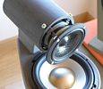
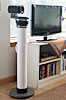
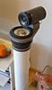
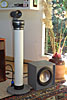
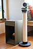
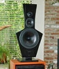
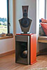
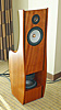
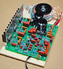
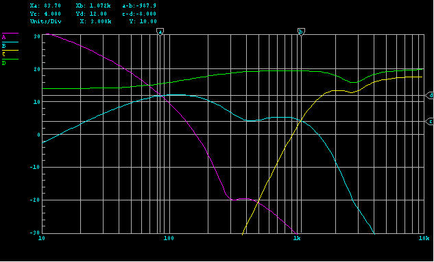